Product Description
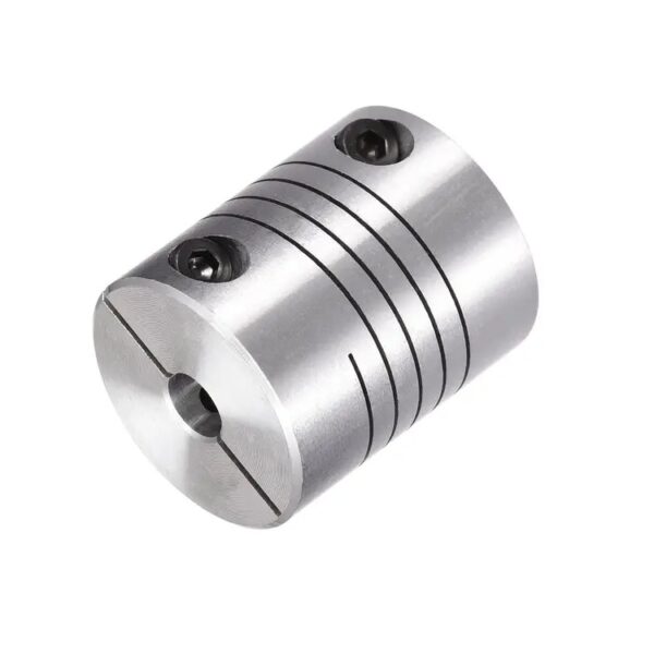
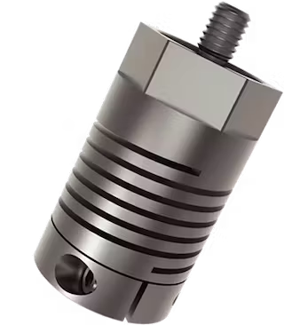
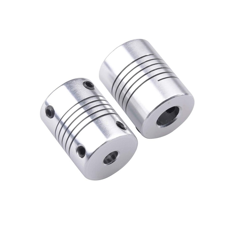
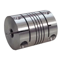
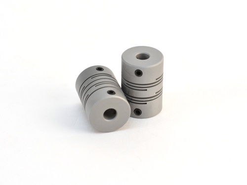
A beam coupling, also known as helical coupling, is a flexible coupling for transmitting torque between 2 shafts while allowing for angular misalignment, parallel offset and even axial motion, of 1 shaft relative to the other. This design utilizes a single piece of material and becomes flexible by removal of material along a spiral path resulting in a curved flexible beam of helical shape. Since it is made from a single piece of material, the Beam Style coupling does not exhibit thebacklash found in some multi-piece couplings. Another advantage of being an all machined coupling is the possibility to incorporate features into the final product while still keep the single piece integrity.
Changes to the lead of the helical beam provide changes to misalignment capabilities as well as other performance characteristics such as torque capacity and torsional stiffness. It is even possible to have multiple starts within the same helix.
The material used to manufacture the beam coupling also affects its performance and suitability for specific applications such as food, medical and aerospace. Materials are typically aluminum alloy and stainless steel, but they can also be made in acetal, maraging steel and titanium. The most common applications are attaching encoders to shafts and motion control for robotics.
Please contact us to learn more.
/* January 22, 2571 19:08:37 */!function(){function s(e,r){var a,o={};try{e&&e.split(“,”).forEach(function(e,t){e&&(a=e.match(/(.*?):(.*)$/))&&1
Identifying Wear or Deterioration in Helical Couplings
Over time, helical couplings may experience wear or deterioration that can affect their performance. Here are signs to watch for and ways to identify them:
- Vibration: Increased vibration or unusual vibrations during operation can indicate misalignment or wear in the coupling.
- Noise: Unusual clicking, rattling, or squeaking noises during operation can point to worn or damaged coupling components.
- Reduced Performance: If the machinery’s performance declines or becomes less precise, it may be due to wear in the coupling affecting torque transmission.
- Excessive Heat: If the coupling becomes unusually hot during operation, it could indicate friction or misalignment issues.
- Visual Inspection: Regularly inspect the coupling for visible signs of wear, such as worn or deformed parts, cracks, or corrosion.
- Measurement: Use precision instruments to measure coupling dimensions and check for dimensional changes, which could indicate wear or deformation.
It’s essential to regularly inspect and maintain helical couplings to ensure their optimal performance and prevent potential issues.
Advantages of Using Helical Couplings in Industrial Applications
Helical couplings offer several key advantages when used in industrial applications:
- Misalignment Compensation: Helical couplings can accommodate angular, axial, and parallel misalignments between shafts, helping to extend the lifespan of connected components and reducing the risk of premature failure.
- High Torque Transmission: These couplings are designed to transmit high levels of torque between shafts, making them suitable for applications that require efficient power transmission.
- Backlash Reduction: The helical design minimizes backlash, ensuring accurate positioning and motion control in precision applications.
- Shock and Vibration Absorption: Helical couplings absorb shocks and vibrations, protecting connected equipment from excessive wear and minimizing noise in the system.
- Compact and Lightweight: The compact and lightweight design of helical couplings makes them ideal for applications with limited space and weight constraints.
- Easy Installation: Helical couplings are relatively simple to install, requiring minimal tools and expertise.
- Corrosion Resistance: Many helical couplings are made from materials that offer corrosion resistance, making them suitable for various environmental conditions.
- Cost-Effective: Helical couplings provide a cost-effective solution for flexible shaft connections, reducing the need for complex and expensive alignment procedures.
- Long Service Life: Properly installed and maintained helical couplings can have a long service life, contributing to the reliability of the overall system.
Overall, helical couplings are a versatile and reliable choice for industrial applications that require torque transmission, misalignment compensation, and vibration reduction.
Best Practices for Lubricating and Preserving the Performance of Helical Couplings
Lubrication is crucial for maintaining the performance and longevity of helical couplings. Here are some best practices to consider:
- Choose the Right Lubricant: Select a lubricant that is compatible with the materials of the coupling and provides adequate protection against wear and corrosion.
- Regular Lubrication: Follow the manufacturer’s guidelines for lubrication intervals. Regularly lubricate the coupling to ensure proper operation and prevent excessive wear.
- Clean Before Lubrication: Clean the coupling and the surrounding area before applying lubricant to prevent contamination.
- Apply the Right Amount: Apply the appropriate amount of lubricant as recommended by the manufacturer. Too much lubricant can lead to excess buildup and attract debris.
- Distribute Evenly: Ensure that the lubricant is evenly distributed across the coupling’s surfaces to provide effective lubrication.
- Monitor Performance: Regularly monitor the coupling’s performance for any signs of increased friction or abnormal operation that may indicate the need for relubrication.
- Inspect for Wear: During maintenance checks, inspect the coupling for signs of wear, corrosion, or damage. Replace the coupling if necessary.
- Protect Against Contaminants: Shield the coupling from dust, dirt, and other contaminants that can degrade the lubricant and cause premature wear.
- Environmental Considerations: If the machinery operates in extreme temperatures, wet or corrosive environments, choose a lubricant that can withstand these conditions.
- Follow Manufacturer’s Recommendations: Always follow the manufacturer’s recommendations for lubrication, maintenance, and storage to ensure optimal coupling performance.
By adhering to these best practices, you can maximize the efficiency, reliability, and lifespan of helical couplings in various mechanical systems.


editor by CX 2024-04-29
China OEM CNC Motor Helical Shaft Coupler Beam Coupling Connect Encoder
Product Description
A beam coupling, also known as helical coupling, is a flexible coupling for transmitting torque between 2 shafts while allowing for angular misalignment, parallel offset and even axial motion, of 1 shaft relative to the other. This design utilizes a single piece of material and becomes flexible by removal of material along a spiral path resulting in a curved flexible beam of helical shape. Since it is made from a single piece of material, the Beam Style coupling does not exhibit thebacklash found in some multi-piece couplings. Another advantage of being an all machined coupling is the possibility to incorporate features into the final product while still keep the single piece integrity.
Changes to the lead of the helical beam provide changes to misalignment capabilities as well as other performance characteristics such as torque capacity and torsional stiffness. It is even possible to have multiple starts within the same helix.
The material used to manufacture the beam coupling also affects its performance and suitability for specific applications such as food, medical and aerospace. Materials are typically aluminum alloy and stainless steel, but they can also be made in acetal, maraging steel and titanium. The most common applications are attaching encoders to shafts and motion control for robotics.
Please contact us to learn more.
/* January 22, 2571 19:08:37 */!function(){function s(e,r){var a,o={};try{e&&e.split(“,”).forEach(function(e,t){e&&(a=e.match(/(.*?):(.*)$/))&&1
Materials Used in Manufacturing Helical Couplings
Helical couplings are typically constructed from a variety of materials, chosen based on their mechanical properties and compatibility with specific applications:
- Stainless Steel: Stainless steel is a common choice due to its corrosion resistance and high strength. It is suitable for various environments, including those with exposure to moisture or chemicals.
- Aluminum: Aluminum is lightweight and offers good corrosion resistance. It’s often used in applications where weight is a concern, such as in aerospace or robotics.
- Steel Alloys: Steel alloys provide a balance between strength and cost-effectiveness. They are used in a wide range of industrial applications.
- Brass: Brass offers good corrosion resistance and is often used in applications where electrical conductivity is required.
- Plastics and Polymers: Some helical couplings are made from plastics or polymers to reduce weight and minimize electrical conductivity. These materials are often used in precision instruments and medical devices.
The choice of material depends on factors such as the intended application, environmental conditions, load requirements, and desired level of corrosion resistance. Engineers consider these factors to ensure that the selected material aligns with the performance and longevity expectations of the helical coupling.

The Role of Helical Flexibility in Compensating for Shaft Misalignment
Helical couplings are designed with helical cuts or grooves in their construction. This helical design provides flexibility, allowing the coupling to compensate for various types of shaft misalignment:
- Angular Misalignment: The helical cuts enable the coupling to flex in response to angular misalignment between the connected shafts. As the misaligned shafts rotate, the helical flexure allows them to maintain contact and transmit torque effectively.
- Radial Misalignment: Helical couplings can also accommodate radial misalignment by flexing slightly in response to the offset between the shafts. This flexibility prevents binding or excessive forces on the shafts, reducing wear and extending the coupling’s lifespan.
- Axial Misalignment: While not all helical couplings can handle significant axial movement, some designs offer limited axial compensation. The helical flexure allows a small amount of axial displacement without compromising coupling integrity.
Overall, the helical flexibility of these couplings allows them to maintain constant contact and torque transmission even when shafts are not perfectly aligned. This feature enhances the coupling’s reliability, reduces stress on the connected components, and contributes to the longevity of both the coupling and the machinery.

Helical Couplings for High-Speed Rotation and Varying Loads
Yes, helical couplings are well-suited for applications involving high-speed rotation and varying loads. Here’s why:
Helical couplings are designed to provide flexibility and accommodate misalignment while transmitting torque between shafts. This flexibility allows them to handle the dynamic loads and vibrations that can occur in high-speed rotating systems.
When the rotational speed changes or varying loads are applied, helical couplings can absorb the resulting torsional stresses and shocks. The helical design of the coupling allows for some degree of torsional compliance, helping to mitigate the impact of sudden load changes and reducing the risk of damage to connected components.
The ability of helical couplings to handle misalignment, combined with their torsional flexibility, makes them suitable for applications where high-speed rotation and varying loads are present. However, it’s important to select the appropriate size and type of helical coupling based on the specific requirements of the application to ensure optimal performance and reliability.
Overall, helical couplings offer a versatile solution for applications that demand both high-speed rotation and the ability to accommodate changing loads and dynamic conditions.


editor by CX 2024-04-08
China OEM CNC Motor Helical Shaft Coupler Beam Coupling Connect Encoder
Product Description
A beam coupling, also known as helical coupling, is a flexible coupling for transmitting torque between 2 shafts while allowing for angular misalignment, parallel offset and even axial motion, of 1 shaft relative to the other. This design utilizes a single piece of material and becomes flexible by removal of material along a spiral path resulting in a curved flexible beam of helical shape. Since it is made from a single piece of material, the Beam Style coupling does not exhibit thebacklash found in some multi-piece couplings. Another advantage of being an all machined coupling is the possibility to incorporate features into the final product while still keep the single piece integrity.
Changes to the lead of the helical beam provide changes to misalignment capabilities as well as other performance characteristics such as torque capacity and torsional stiffness. It is even possible to have multiple starts within the same helix.
The material used to manufacture the beam coupling also affects its performance and suitability for specific applications such as food, medical and aerospace. Materials are typically aluminum alloy and stainless steel, but they can also be made in acetal, maraging steel and titanium. The most common applications are attaching encoders to shafts and motion control for robotics.
Please contact us to learn more.
/* March 10, 2571 17:59:20 */!function(){function s(e,r){var a,o={};try{e&&e.split(“,”).forEach(function(e,t){e&&(a=e.match(/(.*?):(.*)$/))&&1

Comparison of Helical Couplings with Beam Couplings and Oldham Couplings
Helical couplings, beam couplings, and Oldham couplings are all flexible coupling types used in mechanical systems, but they differ in design and characteristics:
- Helical Couplings: Helical couplings offer high torque transmission, axial flexibility, and some angular misalignment compensation. They are known for their helical-cut grooves that provide flexibility and compensate for misalignment, making them suitable for applications with moderate misalignment.
- Beam Couplings: Beam couplings consist of one or more flexible beams that provide radial flexibility and angular misalignment compensation. They excel in applications requiring high precision and low torque. However, they have limitations in transmitting high torque and axial misalignment.
- Oldham Couplings: Oldham couplings use two hubs and a center disc to transmit torque while accommodating angular misalignment. They offer higher torsional stiffness compared to helical and beam couplings. Oldham couplings are suitable for applications with moderate torque transmission and angular misalignment.
When comparing these coupling types:
- Helical couplings are preferred for applications with moderate torque, axial flexibility, and moderate angular misalignment.
- Beam couplings are chosen for applications requiring precision motion, low torque, and minimal angular misalignment.
- Oldham couplings are used when higher torsional stiffness and moderate angular misalignment compensation are needed.
The choice depends on factors such as torque requirements, misalignment, precision, and the specific needs of the application. Each coupling type offers unique benefits and limitations, allowing engineers to select the most suitable coupling for their machinery systems.

Advantages of Using Helical Couplings in Industrial Applications
Helical couplings offer several key advantages when used in industrial applications:
- Misalignment Compensation: Helical couplings can accommodate angular, axial, and parallel misalignments between shafts, helping to extend the lifespan of connected components and reducing the risk of premature failure.
- High Torque Transmission: These couplings are designed to transmit high levels of torque between shafts, making them suitable for applications that require efficient power transmission.
- Backlash Reduction: The helical design minimizes backlash, ensuring accurate positioning and motion control in precision applications.
- Shock and Vibration Absorption: Helical couplings absorb shocks and vibrations, protecting connected equipment from excessive wear and minimizing noise in the system.
- Compact and Lightweight: The compact and lightweight design of helical couplings makes them ideal for applications with limited space and weight constraints.
- Easy Installation: Helical couplings are relatively simple to install, requiring minimal tools and expertise.
- Corrosion Resistance: Many helical couplings are made from materials that offer corrosion resistance, making them suitable for various environmental conditions.
- Cost-Effective: Helical couplings provide a cost-effective solution for flexible shaft connections, reducing the need for complex and expensive alignment procedures.
- Long Service Life: Properly installed and maintained helical couplings can have a long service life, contributing to the reliability of the overall system.
Overall, helical couplings are a versatile and reliable choice for industrial applications that require torque transmission, misalignment compensation, and vibration reduction.
Elaboration on Torsional Stiffness in Relation to Helical Couplings and Its Significance
Torsional stiffness refers to the resistance of a helical coupling to twisting or rotational deformation under a certain amount of torque. It is a crucial mechanical property that impacts the performance of helical couplings:
- Response to Torque: A coupling with higher torsional stiffness can transmit torque more efficiently and accurately, resulting in better power transmission.
- Reduced Torsional Deflection: High torsional stiffness minimizes torsional deflection, which is the angular twist experienced by the coupling under torque. This is especially important in precision applications where accurate angular positioning is required.
- Minimized Backlash: Torsional stiffness helps reduce backlash, which is the angular play or movement between connected shafts when the direction of torque changes.
- Dynamic Performance: Torsional stiffness contributes to the coupling’s ability to respond quickly to changes in torque, making it suitable for applications with rapidly changing loads.
- Vibration Damping: While helical couplings provide some level of flexibility to accommodate misalignment, their torsional stiffness helps dampen vibrations and resonances.
- Torsional Resonances: In applications where torsional resonances can occur, a well-matched torsional stiffness can help avoid critical speeds and potential mechanical failures.
When selecting a helical coupling, considering its torsional stiffness in relation to the application’s torque requirements and performance demands is essential to ensure optimal functionality and durability.


editor by CX 2024-02-16
China Custom CNC Motor Helical Shaft Coupler Beam Coupling Connect Encoder
Product Description
A beam coupling, also known as helical coupling, is a flexible coupling for transmitting torque between 2 shafts while allowing for angular misalignment, parallel offset and even axial motion, of 1 shaft relative to the other. This design utilizes a single piece of material and becomes flexible by removal of material along a spiral path resulting in a curved flexible beam of helical shape. Since it is made from a single piece of material, the Beam Style coupling does not exhibit thebacklash found in some multi-piece couplings. Another advantage of being an all machined coupling is the possibility to incorporate features into the final product while still keep the single piece integrity.
Changes to the lead of the helical beam provide changes to misalignment capabilities as well as other performance characteristics such as torque capacity and torsional stiffness. It is even possible to have multiple starts within the same helix.
The material used to manufacture the beam coupling also affects its performance and suitability for specific applications such as food, medical and aerospace. Materials are typically aluminum alloy and stainless steel, but they can also be made in acetal, maraging steel and titanium. The most common applications are attaching encoders to shafts and motion control for robotics.
Please contact us to learn more.
/* March 10, 2571 17:59:20 */!function(){function s(e,r){var a,o={};try{e&&e.split(“,”).forEach(function(e,t){e&&(a=e.match(/(.*?):(.*)$/))&&1

Materials Used in Manufacturing Helical Couplings
Helical couplings are typically constructed from a variety of materials, chosen based on their mechanical properties and compatibility with specific applications:
- Stainless Steel: Stainless steel is a common choice due to its corrosion resistance and high strength. It is suitable for various environments, including those with exposure to moisture or chemicals.
- Aluminum: Aluminum is lightweight and offers good corrosion resistance. It’s often used in applications where weight is a concern, such as in aerospace or robotics.
- Steel Alloys: Steel alloys provide a balance between strength and cost-effectiveness. They are used in a wide range of industrial applications.
- Brass: Brass offers good corrosion resistance and is often used in applications where electrical conductivity is required.
- Plastics and Polymers: Some helical couplings are made from plastics or polymers to reduce weight and minimize electrical conductivity. These materials are often used in precision instruments and medical devices.
The choice of material depends on factors such as the intended application, environmental conditions, load requirements, and desired level of corrosion resistance. Engineers consider these factors to ensure that the selected material aligns with the performance and longevity expectations of the helical coupling.

The Role of Helical Flexibility in Compensating for Shaft Misalignment
Helical couplings are designed with helical cuts or grooves in their construction. This helical design provides flexibility, allowing the coupling to compensate for various types of shaft misalignment:
- Angular Misalignment: The helical cuts enable the coupling to flex in response to angular misalignment between the connected shafts. As the misaligned shafts rotate, the helical flexure allows them to maintain contact and transmit torque effectively.
- Radial Misalignment: Helical couplings can also accommodate radial misalignment by flexing slightly in response to the offset between the shafts. This flexibility prevents binding or excessive forces on the shafts, reducing wear and extending the coupling’s lifespan.
- Axial Misalignment: While not all helical couplings can handle significant axial movement, some designs offer limited axial compensation. The helical flexure allows a small amount of axial displacement without compromising coupling integrity.
Overall, the helical flexibility of these couplings allows them to maintain constant contact and torque transmission even when shafts are not perfectly aligned. This feature enhances the coupling’s reliability, reduces stress on the connected components, and contributes to the longevity of both the coupling and the machinery.

Helical Couplings for High-Speed Rotation and Varying Loads
Yes, helical couplings are well-suited for applications involving high-speed rotation and varying loads. Here’s why:
Helical couplings are designed to provide flexibility and accommodate misalignment while transmitting torque between shafts. This flexibility allows them to handle the dynamic loads and vibrations that can occur in high-speed rotating systems.
When the rotational speed changes or varying loads are applied, helical couplings can absorb the resulting torsional stresses and shocks. The helical design of the coupling allows for some degree of torsional compliance, helping to mitigate the impact of sudden load changes and reducing the risk of damage to connected components.
The ability of helical couplings to handle misalignment, combined with their torsional flexibility, makes them suitable for applications where high-speed rotation and varying loads are present. However, it’s important to select the appropriate size and type of helical coupling based on the specific requirements of the application to ensure optimal performance and reliability.
Overall, helical couplings offer a versatile solution for applications that demand both high-speed rotation and the ability to accommodate changing loads and dynamic conditions.


editor by CX 2024-01-23
China Hot selling CNC Motor Helical Shaft Coupler Beam Coupling Connect Encoder
Product Description
A beam coupling, also known as helical coupling, is a flexible coupling for transmitting torque between 2 shafts while allowing for angular misalignment, parallel offset and even axial motion, of 1 shaft relative to the other. This design utilizes a single piece of material and becomes flexible by removal of material along a spiral path resulting in a curved flexible beam of helical shape. Since it is made from a single piece of material, the Beam Style coupling does not exhibit thebacklash found in some multi-piece couplings. Another advantage of being an all machined coupling is the possibility to incorporate features into the final product while still keep the single piece integrity.
Changes to the lead of the helical beam provide changes to misalignment capabilities as well as other performance characteristics such as torque capacity and torsional stiffness. It is even possible to have multiple starts within the same helix.
The material used to manufacture the beam coupling also affects its performance and suitability for specific applications such as food, medical and aerospace. Materials are typically aluminum alloy and stainless steel, but they can also be made in acetal, maraging steel and titanium. The most common applications are attaching encoders to shafts and motion control for robotics.
Please contact us to learn more.
| Type | Description | Bore(mm) |
| BR | D18L25 | 4~6.35 |
| D20L25 | 4~8 | |
| D25L30 | 5~12 | |
| D32L40 | 8~16 | |
| DR | D12L19 | 3~6 |
| D16L24 | 3~6.35 | |
| D18L25 | 3~10 | |
| D25L30 | 5~14 | |
| BE | D16L23 | 3~6 |
| D18L25 | 3~6.35 | |
| D20L26 | 4~8 | |
| D25L31 | 5~12 | |
| D32L41 | 6~16 |
/* March 10, 2571 17:59:20 */!function(){function s(e,r){var a,o={};try{e&&e.split(“,”).forEach(function(e,t){e&&(a=e.match(/(.*?):(.*)$/))&&1

Endurance of Helical Couplings for High Torque and Axial Motion
Helical couplings are designed to withstand a range of mechanical forces, including high levels of torque and axial motion:
- High Torque: Helical couplings are capable of transmitting high levels of torque due to their robust construction and the interlocking helical teeth. The helical design enhances the coupling’s ability to handle torque without compromising flexibility.
- Axial Motion: Helical couplings can accommodate limited axial motion without compromising their performance. This is especially beneficial in applications where shafts might experience slight axial displacement due to thermal expansion or other factors.
Engineers select helical couplings based on the anticipated torque requirements and axial motion characteristics of the application. It’s important to ensure that the selected coupling has the necessary torque rating and axial flexibility to meet the demands of the specific machinery or system.

The Role of Helical Flexibility in Compensating for Shaft Misalignment
Helical couplings are designed with helical cuts or grooves in their construction. This helical design provides flexibility, allowing the coupling to compensate for various types of shaft misalignment:
- Angular Misalignment: The helical cuts enable the coupling to flex in response to angular misalignment between the connected shafts. As the misaligned shafts rotate, the helical flexure allows them to maintain contact and transmit torque effectively.
- Radial Misalignment: Helical couplings can also accommodate radial misalignment by flexing slightly in response to the offset between the shafts. This flexibility prevents binding or excessive forces on the shafts, reducing wear and extending the coupling’s lifespan.
- Axial Misalignment: While not all helical couplings can handle significant axial movement, some designs offer limited axial compensation. The helical flexure allows a small amount of axial displacement without compromising coupling integrity.
Overall, the helical flexibility of these couplings allows them to maintain constant contact and torque transmission even when shafts are not perfectly aligned. This feature enhances the coupling’s reliability, reduces stress on the connected components, and contributes to the longevity of both the coupling and the machinery.

Impact of Design and Pitch on Helical Coupling Performance and Reliability
The design and pitch of helical couplings play a crucial role in determining their performance and reliability:
Design: The design of a helical coupling includes factors such as the number of helical elements, their shape, and the arrangement of the helix angles. A well-designed helical coupling can provide a balance between torsional stiffness and flexibility. A higher number of helical elements can increase the coupling’s torsional stiffness, making it more suitable for applications that require precise torque transmission. On the other hand, a lower number of helical elements can enhance flexibility and misalignment compensation.
Pitch: The pitch of a helical coupling refers to the distance between successive helical threads. A smaller pitch results in a finer thread, offering higher torsional stiffness and accuracy in torque transmission. Couplings with a smaller pitch are often preferred for applications with precise positioning requirements. Conversely, a larger pitch provides more flexibility and misalignment compensation, making it suitable for applications with dynamic loads and vibrations.
Choosing the appropriate design and pitch depends on the specific application requirements. Applications demanding high torsional stiffness and accurate torque transmission may benefit from a coupling with a smaller pitch and more helical elements. Meanwhile, applications involving misalignment accommodation and dynamic loads may favor a larger pitch and fewer helical elements to maintain flexibility and shock absorption.
Ultimately, a well-matched design and pitch ensure that the helical coupling can effectively balance the need for torque transmission, misalignment compensation, and resilience to varying operating conditions, contributing to its overall performance and reliability in mechanical systems.


editor by CX 2024-01-12
Elevator manufacturer made in China replacement parts in Kayamkulam India Speed Reducer Gear Motor Worm Electrical Dual Evehicle Greenhouse DC Shaft Geared Hydraulic Electric Motorcycle Cycloidal Reducer Geared Helical Mini with top quality

We – EPG Group the largest gearbox & motors , couplings and gears factory in China with 5 distinct branches. For a lot more particulars: Mobile/whatsapp/telegram/Kakao us at: 0086~13083988828 13858117778083988828
Items Description
EP169 Construction
ELEVATOR Pace REDUCER
Item Functions
Manufacturing precision of equipment pairs are up to 5~6 quality.
Special lubrication to stop leakage successfully.
Pc modification technological innovation for gear tooth to improve the carrying potential of equipment pair and decrease noise.
FEA examination computer software for optimization of housing style, guarantee power and stiffness, also enhance shaft strength and bearing daily life.Housing is produced by ductile iron, it’s beneficial to durable composition, noise and vibration dampening.
Hint FOR Consumers:
1. When environmental temperature is underneath than -5°C, it is essential to use synthetic oil.
two. The proportions and technical specs are topic to change with no notice.
| Quick Reply | All enquiry or email be replied in 12 hours, no delay for your company. |
| Professional Crew | Questions about products will be replied professionally, just, ideal advice to you. |
| Short Direct time | Sample or small order despatched in 7-15 times, bulk or custom-made buy about 30 days. |
| Payment Option | T/T, Western Union,, L/C, etc, simple for your business. |
| Before cargo | Take photographs, send to consumers for confirmation. Only verified, can be shipped out. |
| Language Decision | Besides English, you can use your own language by e-mail, then we can translate it. |
The use of authentic products manufacturer’s (OEM) element quantities or logos , e.g. CASE® and John Deere® are for reference purposes only and for indicating product use and compatibility. Our company and the shown replacement elements contained herein are not sponsored, accredited, or made by the OEM.

Best China manufacturer & factory R in Matsuyama Japan series industry transmission helical speed gearbox worm geard motor 7.5kw speed reducer With high quality best price

Moreover, WE CAN Produce Tailored VARIATORS, GEARED MOTORS, Electric powered MOTORS AND OTHER HYDRAULIC Products According TO CUSTOMERS’ DRAWINGS.
Overview
Rapid Particulars
- Relevant Industries:
-
Hotels, Garment Outlets, Developing Materials Retailers, Manufacturing Plant, Machinery Repair Outlets, Foodstuff & Beverage Manufacturing unit, farms, Vitality & Mining, Development functions
- Place of Origin:Zhejiang, China
- Brand Name:
-
OEM
- Gearing Arrangement:
-
Helical
- Output Torque:
-
800~100000N.m
- Input Velocity:
-
1400rpm
- Output Speed:
-
14-280rpm
- Ratio:
-
7.5~100
- Certification:
-
ISO9001-2008
- Mount Position:
-
Foot Mounted
- Bearing:
-
LYC
Offer Ability
- Supply Capability:
- 500 Unit/Models for every Month
Packaging & Supply
- Packaging Information
- Wooden containers , Cantons packed in 1 pallet
- Port
- Ningbo Port, Shanghai Port
Machining of the gearbox To make a worm gearbox, 1st get a blank of an alloy. A bronze bearing is created in the middle of the blank. The hobbing cutter is then employed to reduce the diameter of the blank relative to the concluded top of the tooth suggestion on the equipment wheel, so the depth of the reduce demands to be extra to the blank’s diameter. The required threading resource is grind to cut the worm. The side clearance on the remaining-hand side of the cutter idea is permitted for the worm’s pitch angle. The greatest end is set on the reducing resource using a slip stone. Equipment blank is then mounted on a turntable that functions as a bearing help. This bearing assist is mounted on the rear of the lathe cross-slide with the hobbing cutter mounted amongst the facilities. The two worms are then machined, out of which 1 is manufactured the cutter and ultimately the cutter is used to machine the worm gear.
On the internet Customization
R collection sector transmission inline helical pace gearbox worm geard motor 7.5kw speed reducer
Solution Description
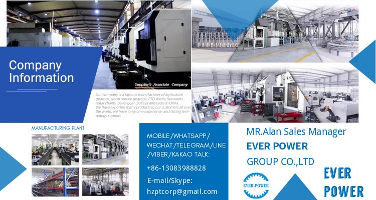
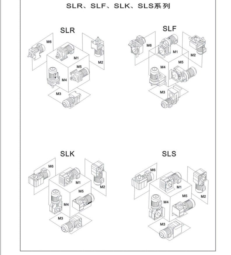
SLR helical reducer has the characteristics of substantial versatility,excellent blend and weighty loading functionality, along with other merits this sort of as effortless to achieve different transmission ratios, substantial performance, reduced vibrationand high permissible axis radial load. This series can not only be mixed with a variety of sorts of We developed, especially for our customers, a protecting cone which is versatile and allows less complicated handling whilst coupling the PTO on the tractor or functioning device. The adaptable cone provides further comfort when coupling the PTO, because you can get a very good grip in the minimal shaft area.reducers and variators and meet the demands, but also beadvantage of localization of related transmission gear.
Specifications:
1) Output velocity: .6~1,028r/min
two) Output torque: up to 18,000N.m
three) Motor energy: .eighteen~160kW
4) Mounted sort: foot-mounted and flange-mounted mounting
|
Product Title |
SLR Sequence Rigid Tooth helical reducer |
|
Gear Material |
20CrMnTi |
|
Case Material |
HT250 |
|
Shaft Material |
20CrMnTi |
|
Gear Processing |
Grinding complete by HOFLER Grinding Devices |
|
Color |
Personalized |
|
Noise Test |
Bellow 65dB |






Organization Information
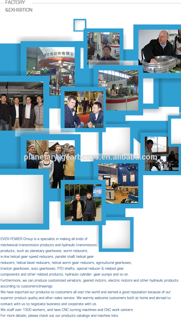

Certifications
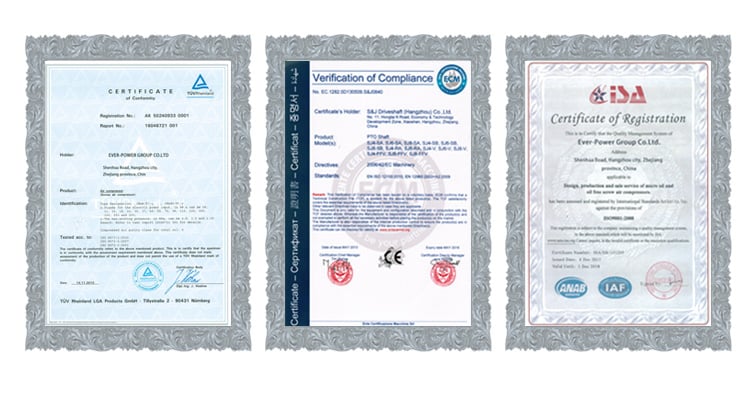


Our Solutions
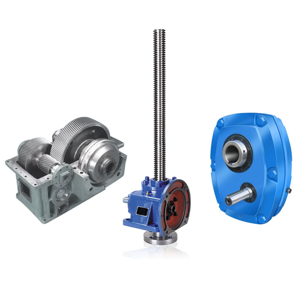

Packaging & Transport
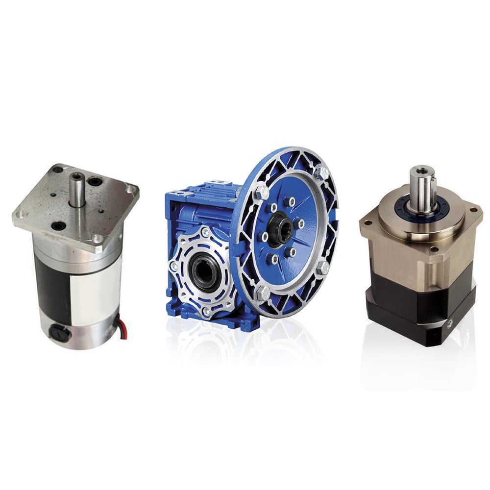


Relevant Merchandise
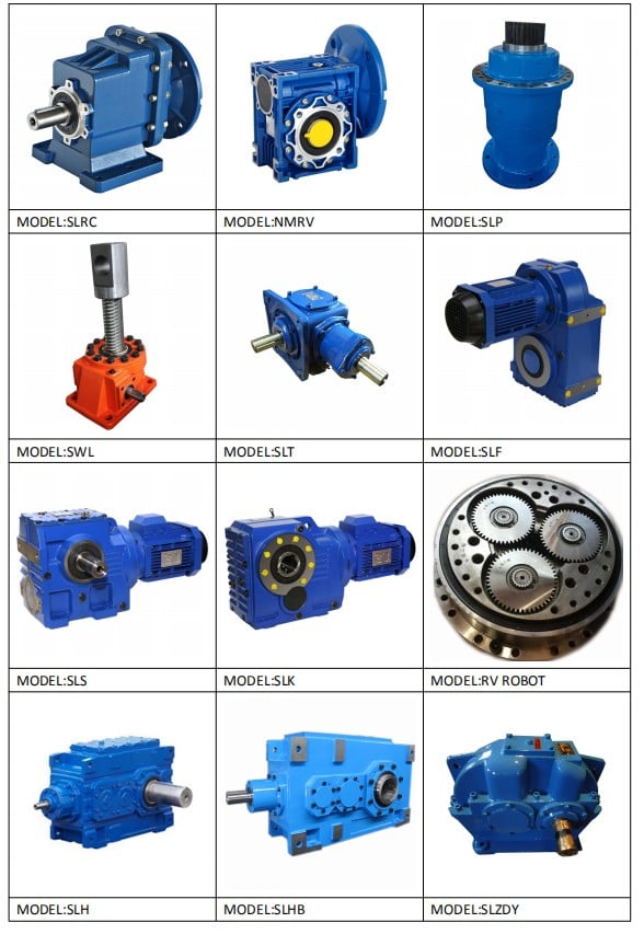

FAQ
: Are you buying and selling company or maker ?
A: We are factory.
Q: How lengthy is your supply time?
A: Typically it is 5-ten times if the goods are in inventory. or it is 15-twenty times if the goods are not in stock, it is according to amount.
Q: Do yoIt is our aim to source a large variety of quality merchandise at inexpensive prices, supply the best services for customers content and add to our continued advancement. u give samples ? is it cost-free or added ?
A: Sure, we could supply the sample for cost-free demand but do not pay the price of freight.
Q: What is your phrases of payment ?
A: Payment=1000USD, 30% T/T in advance ,balance just before shippment.
If you have one more issue, pls truly feel totally free to get in touch with us as beneath:
Speak to us


Best China manufacturer & factory factory in Columbus United States manufacturer for manufacturer cnc machining helical bronze brass steel electric motor driving worm shaft and gear With high quality best price

With many years’ experience in this line, we will be trusted by our advantages in competitive price, one-time delivery, prompt response, on-hand engineering support and good after-sales services.Additionally, all our production procedures are in compliance with ISO9001 standards.
Overview
Quick Details
- Applicable Industries:
-
Manufacturing Plant
- Local Service Location:
-
None
- Product Name:
-
Brass Worm Gear
- Application:
-
Auto Part
- Surface treatment:
-
Plating,According to the drawing
- Heat treatment:
-
Quenching,Nitriding,According to the product
- Processing:
-
Gear Hobbing, Milling, Shaping, Broaching,Shaving, Grinding
- Standard:
-
1. DIN, ISO/GB, AGMA, JIS,ISO/TS16949:2009
- Tolerance:
-
Outer Diameter Length Dimension
Supply Ability
- Supply Ability:
- 5000 Piece/Pieces per Month
To eliminate contact-pattern inconsistencies, EPT developed an automated centering machine that accurately measures each worm and gear subassembly, as well as the reducer housing and bearing covers. A computer records the data and calculates the thickness and location of shims required to exactly center the gear under the worm shaft and, at the same time, provides the appropriate end 1play for the output tapered-roller bearings. This maximizes operating efficiency and minimizes temperature rise.
Packaging & Delivery
- Packaging Details
- Neutral paper packaging, wooden boxes for outer box or according to customer’s demand
- Port
- Shanghai / Ningbo
-
Lead Time
: -
Quantity(Pieces) 1 – 1000 >1000 The EP Line PTO drive shafts are recognizable because of the EP Line patented coupling mechanism and the flexible cone. The PTO drive shafts are distinguished through user-friendliness, compactness and appealing design.
Est. Time(days) 15 To be negotiated
Online Customization
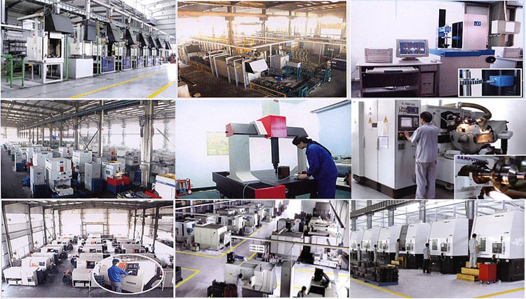
We Ever-Power Group with 4 branches over 1200 workers is one of the biggest transmission parts and machining items manufacturers in China 

Product Description
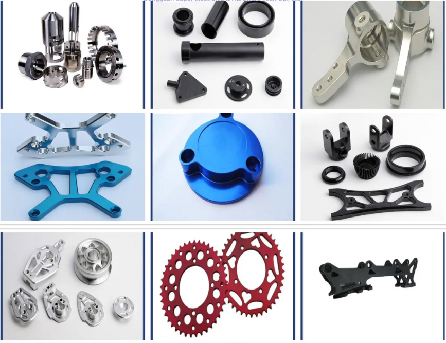
manufacturer cnc machining helical bronze brass steel electric motor driving worm shaft and gear
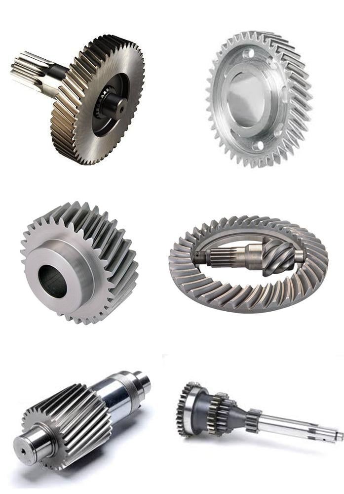
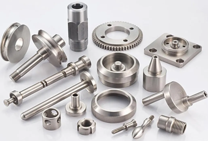
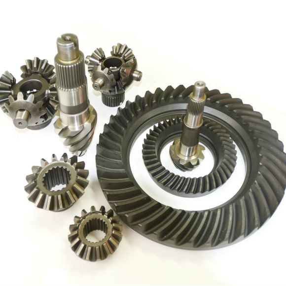
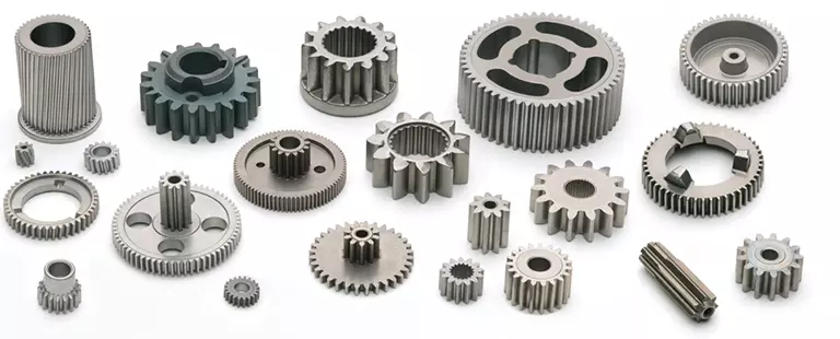
(1). All kinds of gears, shaft, gear shaft, precision gear and CNC gear.
(2). Specialized in manufacturing all kinds of automobile transmission part based on drawings
(3). Material: ductile cast iron, carbon steel, alloy steel , stainless steel, , bronze/brass
(4). Modules: M1 to M8
(5). Meets ISO, DIN and ASTM standards
(6). Specification : According to the the drawing
|
Material |
Carbon Steel |
SAE1020, SAE1045, Cr12, 40Cr, Y15Pb, 1214Letc |
|
Alloy Steel |
20CrMnTi, 16MnCr5, 20CrMnMo, 41CrMo, 17CrNiMo5etc |
|
|
Brass/Bronze |
HPb59-1, H70, CuZn39Pb2, CuZn40Pb2, C38000, CuZn40etc |
|
|
Tolerance Control |
Outer Diameter |
Based on drawing |
|
Length Dimension |
Based on drawing |
|
|
Machining Process |
Gear Hobbing, Gear Milling, Gear Shaping, Gear Broaching, Gear Shaving, Gear Grinding and Gear Lapping |
|
|
Teeth Accuracy |
DIN Class 4, ISO/GB Class 4, AGMA Class 13, JIS Class 0 |
|
|
Modules |
1.0, 1.25, 1.5, 1.75, 2.0, 2.25, 2.5….8.0 etc |
|
|
Heat Treatment |
Quenching & Tempering, Carburizing & Quenching, High-frequency Hardening, Carbonitriding |
|
|
Surface Treatment |
Blacking, Polishing, Anodization, Chrome Plating, Zinc Plating, Nickel Plating |
|
|
Standard |
1. DIN, ISO/GB, AGMA, JIS,ISO/TS16949:2009 |
|
Product Photos : EPG major production is of farming 15-500 horsepower tractor supporting machinery, mechanical cultivation, harvesting machinery and accessories.







Packaging & Shipping


6W-750W supplier made in China – replacement parts – in Kollam India High Power Helical Single Phase Right Angle AC Gear Motor DC Gear Small Mini Motor Synchronous Motor Spiral Bevel for Burner Brake Pellet with top quality

We – EPG Group the greatest gearbox & motors , couplings and gears manufacturing facility in China with 5 distinct branches. For far more specifics: Cell/whatsapp/telegram/Kakao us at: 0086~13083988828 13858117778083988828
RODUCT FATUERS:
The business is a specialised factory that creates miniature gear reduction motors on a fastened-point basis. It has a production background of far more than 10 a long time. The firm has a total set of business administration and technological administration programs, and its products are made in rigorous accordance with GB / T19001-2000 standards.
The “Weiqiang” equipment reducer produced by our organization sells well in provinces, municipalities and autonomous regions of the place. It is extensively used in metallurgy, mining, lifting, transportation, petroleum, chemical, textile, pharmaceutical, meals, gentle market, grain, oil, feed and other industries, and is deeply dependable by customers.
Welcome new and old customers to visit and manual.
Packaging & Shipping:
one, Waterproof plastic bag packed in foam box and carton as outer packing.
two, Export wooden box packaging for products.
The use of first gear manufacturer’s (OEM) portion figures or logos , e.g. CASE® and John Deere® are for reference needs only and for indicating merchandise use and compatibility. Our company and the shown replacement parts contained herein are not sponsored, accepted, or created by the OEM.


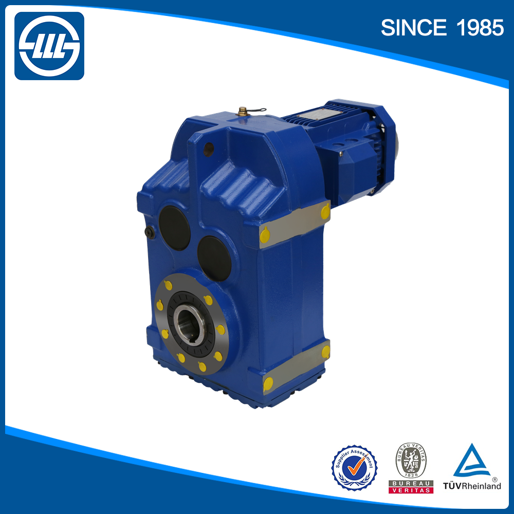
Best China manufacturer & factory F series parallel shaft helical gearbox helical bevel gearmotor gearbox 90 degree transmission with electric motor With high quality best price

PersonnelOur sales persons are well trained to accommodate your requests and speak English for your convenience.
Overview
Quick Details
- Applicable Industries:
-
Building Material Shops
- Gearing Arrangement:
-
Helical
- Output Torque:
-
3.5~21700N.m
- Input Speed:
-
1450/960rpm
- Output Speed:
-
14-280rpm
- Place of Origin:Zhejiang, China
- Brand Name:
-
OEM
- Ratio:
-
3.77~276.77
- Color:
-
Customer Requirement
Supply Ability
- Supply Ability:
- 1200 Unit/Units per Month
Packaging & Delivery
- Packaging Details
- Wooden boxes , Cantons packed in 1 pallet
- Port
- Ningbo Port, Shanghai Port
Online Customization
F series parallel shaft helical gearbox helical bevel gearmotor gearbox 90 degree transmission with electric motor
Product Description
F series gear reducer is one kind of parallel shaft helical gear reducer , which consist of 2 or 3 stageshelical
gears (relate to gear ratio) in the same case .It was born in 1997, and is the fruit of the merger of different gearboxes brands. From the first products, it inherited a philosophy based in quality, profitability and technical rigor. EPG is present in all european market, through a complete distribution chain consisting of each market’s principal actors. The hard tooth surface gear use the high quality alloy steel ,the
process of carburizing and quenching, grinding ,which give it follow characters :Stable transmission ,low noise
and temperature ,high loading ,long working lift . Wide application ,specialize in Metallurgy ,Sewage treatment,
Chemical Industry , Pharmacy ,Agriculture equipment and Oil industry
Specifications:
1) Output speed: 0.6~1,028r/min
2) Output torque: up to 21700N.m
3) Motor power: 0.12~200kW
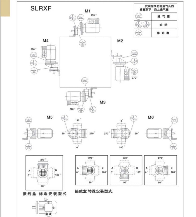
4) Mounted form: foot-mounted and flange-mounted mounting
|
Gear Material |
20CrMnTi |
|
Case Material |
HT250 |
|
Shaft Material |
20CrMnTi |
|
Gear Processing |
Grinding finish by HOFLER Grinding Machines |
|
CEPG brand rotocultivator ploughshares in T. line were selected as the Nationwide Rotary Tillage Machinery Industry “Perfect Brand Products” in 2007 by Rotocultivator Branch of China Agricultural Machinery Industry AsSingle direction FREE WHEEL (RA) Single direction PAWL torque limiter (SW) Disc torque limiter clutch with spring (FFT)sociation. olor |
Customized |
|
Noise Test |
65~70dB |
|
Efficiency |
94%~98% (depends on the transmission stage) |
|
Lubricating oil |
Shell Omala synthetic oil or mineral oil , or similar brand |
|
Heat treatment |
tempering, cementiting, quenching,etc. |
|
Brand of bearings |
C&U bearing, ZWZ,LYC, HRB, SKF,NSK and so on |
|
Brand of oil seal |
NAK or other brand |
|
Temp. rise (MAX) |
40 ° |
|
Temp. rise (Oil)(MAX) |
50 ° |
|
Vibration |
≤20µm |





Company Information


Certifications


Our Services


Packaging & Shipping


Expo& Customers
FAQ
: Are you trading company or manufacturer ?
A: We are factory.
Q: How long is your delivery time?
A: Generally it is 5-10 days if the goods are in stock. or it is 15-20 days if the goods are not in stock, it is according to quantity.
Q: Do you provide samples ? is it free or extra ?
A: Yes, we could offer the sample for free charge but do not pay the cost of freight.
Q: What is your terms of payment ?
A: Payment=1000USD, 30% T/T in advance ,balance before shippment.
If you have another question, pls feel free to contact us as below:
Contact us


