Product Description
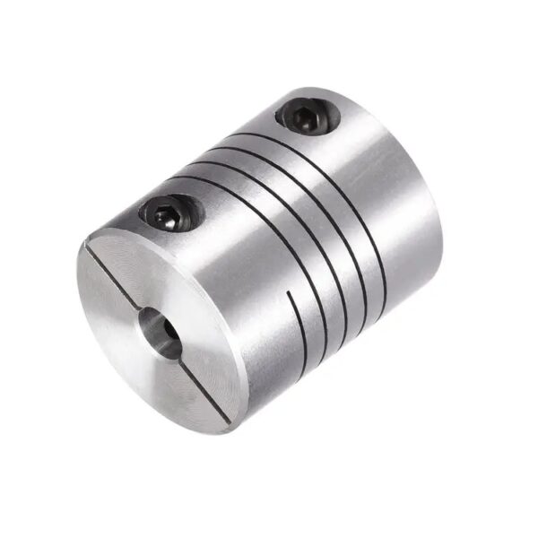
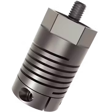
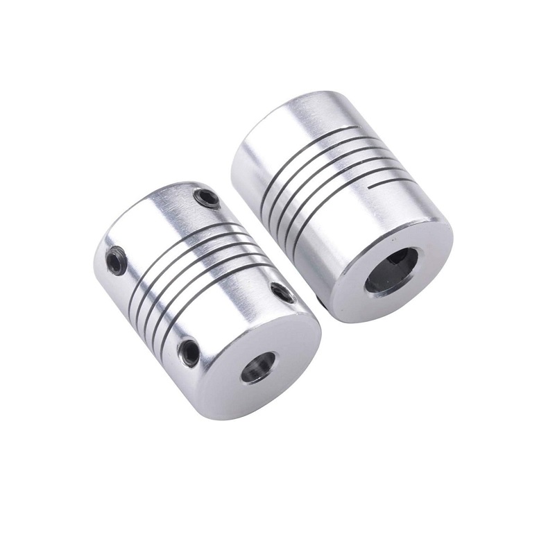
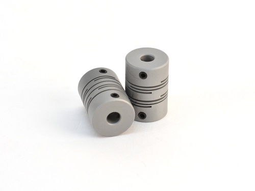
A beam coupling, also known as helical coupling, is a flexible coupling for transmitting torque between 2 shafts while allowing for angular misalignment, parallel offset and even axial motion, of 1 shaft relative to the other. This design utilizes a single piece of material and becomes flexible by removal of material along a spiral path resulting in a curved flexible beam of helical shape. Since it is made from a single piece of material, the Beam Style coupling does not exhibit thebacklash found in some multi-piece couplings. Another advantage of being an all machined coupling is the possibility to incorporate features into the final product while still keep the single piece integrity.
Changes to the lead of the helical beam provide changes to misalignment capabilities as well as other performance characteristics such as torque capacity and torsional stiffness. It is even possible to have multiple starts within the same helix.
The material used to manufacture the beam coupling also affects its performance and suitability for specific applications such as food, medical and aerospace. Materials are typically aluminum alloy and stainless steel, but they can also be made in acetal, maraging steel and titanium. The most common applications are attaching encoders to shafts and motion control for robotics.
Please contact us to learn more.
/* January 22, 2571 19:08:37 */!function(){function s(e,r){var a,o={};try{e&&e.split(“,”).forEach(function(e,t){e&&(a=e.match(/(.*?):(.*)$/))&&1
Identifying Wear or Deterioration in Helical Couplings
Over time, helical couplings may experience wear or deterioration that can affect their performance. Here are signs to watch for and ways to identify them:
- Vibration: Increased vibration or unusual vibrations during operation can indicate misalignment or wear in the coupling.
- Noise: Unusual clicking, rattling, or squeaking noises during operation can point to worn or damaged coupling components.
- Reduced Performance: If the machinery’s performance declines or becomes less precise, it may be due to wear in the coupling affecting torque transmission.
- Excessive Heat: If the coupling becomes unusually hot during operation, it could indicate friction or misalignment issues.
- Visual Inspection: Regularly inspect the coupling for visible signs of wear, such as worn or deformed parts, cracks, or corrosion.
- Measurement: Use precision instruments to measure coupling dimensions and check for dimensional changes, which could indicate wear or deformation.
It’s essential to regularly inspect and maintain helical couplings to ensure their optimal performance and prevent potential issues.
Advantages of Using Helical Couplings in Industrial Applications
Helical couplings offer several key advantages when used in industrial applications:
- Misalignment Compensation: Helical couplings can accommodate angular, axial, and parallel misalignments between shafts, helping to extend the lifespan of connected components and reducing the risk of premature failure.
- High Torque Transmission: These couplings are designed to transmit high levels of torque between shafts, making them suitable for applications that require efficient power transmission.
- Backlash Reduction: The helical design minimizes backlash, ensuring accurate positioning and motion control in precision applications.
- Shock and Vibration Absorption: Helical couplings absorb shocks and vibrations, protecting connected equipment from excessive wear and minimizing noise in the system.
- Compact and Lightweight: The compact and lightweight design of helical couplings makes them ideal for applications with limited space and weight constraints.
- Easy Installation: Helical couplings are relatively simple to install, requiring minimal tools and expertise.
- Corrosion Resistance: Many helical couplings are made from materials that offer corrosion resistance, making them suitable for various environmental conditions.
- Cost-Effective: Helical couplings provide a cost-effective solution for flexible shaft connections, reducing the need for complex and expensive alignment procedures.
- Long Service Life: Properly installed and maintained helical couplings can have a long service life, contributing to the reliability of the overall system.
Overall, helical couplings are a versatile and reliable choice for industrial applications that require torque transmission, misalignment compensation, and vibration reduction.
Best Practices for Lubricating and Preserving the Performance of Helical Couplings
Lubrication is crucial for maintaining the performance and longevity of helical couplings. Here are some best practices to consider:
- Choose the Right Lubricant: Select a lubricant that is compatible with the materials of the coupling and provides adequate protection against wear and corrosion.
- Regular Lubrication: Follow the manufacturer’s guidelines for lubrication intervals. Regularly lubricate the coupling to ensure proper operation and prevent excessive wear.
- Clean Before Lubrication: Clean the coupling and the surrounding area before applying lubricant to prevent contamination.
- Apply the Right Amount: Apply the appropriate amount of lubricant as recommended by the manufacturer. Too much lubricant can lead to excess buildup and attract debris.
- Distribute Evenly: Ensure that the lubricant is evenly distributed across the coupling’s surfaces to provide effective lubrication.
- Monitor Performance: Regularly monitor the coupling’s performance for any signs of increased friction or abnormal operation that may indicate the need for relubrication.
- Inspect for Wear: During maintenance checks, inspect the coupling for signs of wear, corrosion, or damage. Replace the coupling if necessary.
- Protect Against Contaminants: Shield the coupling from dust, dirt, and other contaminants that can degrade the lubricant and cause premature wear.
- Environmental Considerations: If the machinery operates in extreme temperatures, wet or corrosive environments, choose a lubricant that can withstand these conditions.
- Follow Manufacturer’s Recommendations: Always follow the manufacturer’s recommendations for lubrication, maintenance, and storage to ensure optimal coupling performance.
By adhering to these best practices, you can maximize the efficiency, reliability, and lifespan of helical couplings in various mechanical systems.


editor by CX 2024-04-29
China OEM CNC Motor Helical Shaft Coupler Beam Coupling Connect Encoder
Product Description
A beam coupling, also known as helical coupling, is a flexible coupling for transmitting torque between 2 shafts while allowing for angular misalignment, parallel offset and even axial motion, of 1 shaft relative to the other. This design utilizes a single piece of material and becomes flexible by removal of material along a spiral path resulting in a curved flexible beam of helical shape. Since it is made from a single piece of material, the Beam Style coupling does not exhibit thebacklash found in some multi-piece couplings. Another advantage of being an all machined coupling is the possibility to incorporate features into the final product while still keep the single piece integrity.
Changes to the lead of the helical beam provide changes to misalignment capabilities as well as other performance characteristics such as torque capacity and torsional stiffness. It is even possible to have multiple starts within the same helix.
The material used to manufacture the beam coupling also affects its performance and suitability for specific applications such as food, medical and aerospace. Materials are typically aluminum alloy and stainless steel, but they can also be made in acetal, maraging steel and titanium. The most common applications are attaching encoders to shafts and motion control for robotics.
Please contact us to learn more.
/* January 22, 2571 19:08:37 */!function(){function s(e,r){var a,o={};try{e&&e.split(“,”).forEach(function(e,t){e&&(a=e.match(/(.*?):(.*)$/))&&1
Materials Used in Manufacturing Helical Couplings
Helical couplings are typically constructed from a variety of materials, chosen based on their mechanical properties and compatibility with specific applications:
- Stainless Steel: Stainless steel is a common choice due to its corrosion resistance and high strength. It is suitable for various environments, including those with exposure to moisture or chemicals.
- Aluminum: Aluminum is lightweight and offers good corrosion resistance. It’s often used in applications where weight is a concern, such as in aerospace or robotics.
- Steel Alloys: Steel alloys provide a balance between strength and cost-effectiveness. They are used in a wide range of industrial applications.
- Brass: Brass offers good corrosion resistance and is often used in applications where electrical conductivity is required.
- Plastics and Polymers: Some helical couplings are made from plastics or polymers to reduce weight and minimize electrical conductivity. These materials are often used in precision instruments and medical devices.
The choice of material depends on factors such as the intended application, environmental conditions, load requirements, and desired level of corrosion resistance. Engineers consider these factors to ensure that the selected material aligns with the performance and longevity expectations of the helical coupling.

The Role of Helical Flexibility in Compensating for Shaft Misalignment
Helical couplings are designed with helical cuts or grooves in their construction. This helical design provides flexibility, allowing the coupling to compensate for various types of shaft misalignment:
- Angular Misalignment: The helical cuts enable the coupling to flex in response to angular misalignment between the connected shafts. As the misaligned shafts rotate, the helical flexure allows them to maintain contact and transmit torque effectively.
- Radial Misalignment: Helical couplings can also accommodate radial misalignment by flexing slightly in response to the offset between the shafts. This flexibility prevents binding or excessive forces on the shafts, reducing wear and extending the coupling’s lifespan.
- Axial Misalignment: While not all helical couplings can handle significant axial movement, some designs offer limited axial compensation. The helical flexure allows a small amount of axial displacement without compromising coupling integrity.
Overall, the helical flexibility of these couplings allows them to maintain constant contact and torque transmission even when shafts are not perfectly aligned. This feature enhances the coupling’s reliability, reduces stress on the connected components, and contributes to the longevity of both the coupling and the machinery.

Helical Couplings for High-Speed Rotation and Varying Loads
Yes, helical couplings are well-suited for applications involving high-speed rotation and varying loads. Here’s why:
Helical couplings are designed to provide flexibility and accommodate misalignment while transmitting torque between shafts. This flexibility allows them to handle the dynamic loads and vibrations that can occur in high-speed rotating systems.
When the rotational speed changes or varying loads are applied, helical couplings can absorb the resulting torsional stresses and shocks. The helical design of the coupling allows for some degree of torsional compliance, helping to mitigate the impact of sudden load changes and reducing the risk of damage to connected components.
The ability of helical couplings to handle misalignment, combined with their torsional flexibility, makes them suitable for applications where high-speed rotation and varying loads are present. However, it’s important to select the appropriate size and type of helical coupling based on the specific requirements of the application to ensure optimal performance and reliability.
Overall, helical couplings offer a versatile solution for applications that demand both high-speed rotation and the ability to accommodate changing loads and dynamic conditions.


editor by CX 2024-04-08
China OEM CNC Motor Helical Shaft Coupler Beam Coupling Connect Encoder
Product Description
A beam coupling, also known as helical coupling, is a flexible coupling for transmitting torque between 2 shafts while allowing for angular misalignment, parallel offset and even axial motion, of 1 shaft relative to the other. This design utilizes a single piece of material and becomes flexible by removal of material along a spiral path resulting in a curved flexible beam of helical shape. Since it is made from a single piece of material, the Beam Style coupling does not exhibit thebacklash found in some multi-piece couplings. Another advantage of being an all machined coupling is the possibility to incorporate features into the final product while still keep the single piece integrity.
Changes to the lead of the helical beam provide changes to misalignment capabilities as well as other performance characteristics such as torque capacity and torsional stiffness. It is even possible to have multiple starts within the same helix.
The material used to manufacture the beam coupling also affects its performance and suitability for specific applications such as food, medical and aerospace. Materials are typically aluminum alloy and stainless steel, but they can also be made in acetal, maraging steel and titanium. The most common applications are attaching encoders to shafts and motion control for robotics.
Please contact us to learn more.
/* March 10, 2571 17:59:20 */!function(){function s(e,r){var a,o={};try{e&&e.split(“,”).forEach(function(e,t){e&&(a=e.match(/(.*?):(.*)$/))&&1

Comparison of Helical Couplings with Beam Couplings and Oldham Couplings
Helical couplings, beam couplings, and Oldham couplings are all flexible coupling types used in mechanical systems, but they differ in design and characteristics:
- Helical Couplings: Helical couplings offer high torque transmission, axial flexibility, and some angular misalignment compensation. They are known for their helical-cut grooves that provide flexibility and compensate for misalignment, making them suitable for applications with moderate misalignment.
- Beam Couplings: Beam couplings consist of one or more flexible beams that provide radial flexibility and angular misalignment compensation. They excel in applications requiring high precision and low torque. However, they have limitations in transmitting high torque and axial misalignment.
- Oldham Couplings: Oldham couplings use two hubs and a center disc to transmit torque while accommodating angular misalignment. They offer higher torsional stiffness compared to helical and beam couplings. Oldham couplings are suitable for applications with moderate torque transmission and angular misalignment.
When comparing these coupling types:
- Helical couplings are preferred for applications with moderate torque, axial flexibility, and moderate angular misalignment.
- Beam couplings are chosen for applications requiring precision motion, low torque, and minimal angular misalignment.
- Oldham couplings are used when higher torsional stiffness and moderate angular misalignment compensation are needed.
The choice depends on factors such as torque requirements, misalignment, precision, and the specific needs of the application. Each coupling type offers unique benefits and limitations, allowing engineers to select the most suitable coupling for their machinery systems.

Advantages of Using Helical Couplings in Industrial Applications
Helical couplings offer several key advantages when used in industrial applications:
- Misalignment Compensation: Helical couplings can accommodate angular, axial, and parallel misalignments between shafts, helping to extend the lifespan of connected components and reducing the risk of premature failure.
- High Torque Transmission: These couplings are designed to transmit high levels of torque between shafts, making them suitable for applications that require efficient power transmission.
- Backlash Reduction: The helical design minimizes backlash, ensuring accurate positioning and motion control in precision applications.
- Shock and Vibration Absorption: Helical couplings absorb shocks and vibrations, protecting connected equipment from excessive wear and minimizing noise in the system.
- Compact and Lightweight: The compact and lightweight design of helical couplings makes them ideal for applications with limited space and weight constraints.
- Easy Installation: Helical couplings are relatively simple to install, requiring minimal tools and expertise.
- Corrosion Resistance: Many helical couplings are made from materials that offer corrosion resistance, making them suitable for various environmental conditions.
- Cost-Effective: Helical couplings provide a cost-effective solution for flexible shaft connections, reducing the need for complex and expensive alignment procedures.
- Long Service Life: Properly installed and maintained helical couplings can have a long service life, contributing to the reliability of the overall system.
Overall, helical couplings are a versatile and reliable choice for industrial applications that require torque transmission, misalignment compensation, and vibration reduction.
Elaboration on Torsional Stiffness in Relation to Helical Couplings and Its Significance
Torsional stiffness refers to the resistance of a helical coupling to twisting or rotational deformation under a certain amount of torque. It is a crucial mechanical property that impacts the performance of helical couplings:
- Response to Torque: A coupling with higher torsional stiffness can transmit torque more efficiently and accurately, resulting in better power transmission.
- Reduced Torsional Deflection: High torsional stiffness minimizes torsional deflection, which is the angular twist experienced by the coupling under torque. This is especially important in precision applications where accurate angular positioning is required.
- Minimized Backlash: Torsional stiffness helps reduce backlash, which is the angular play or movement between connected shafts when the direction of torque changes.
- Dynamic Performance: Torsional stiffness contributes to the coupling’s ability to respond quickly to changes in torque, making it suitable for applications with rapidly changing loads.
- Vibration Damping: While helical couplings provide some level of flexibility to accommodate misalignment, their torsional stiffness helps dampen vibrations and resonances.
- Torsional Resonances: In applications where torsional resonances can occur, a well-matched torsional stiffness can help avoid critical speeds and potential mechanical failures.
When selecting a helical coupling, considering its torsional stiffness in relation to the application’s torque requirements and performance demands is essential to ensure optimal functionality and durability.


editor by CX 2024-02-16
China Custom CNC Motor Helical Shaft Coupler Beam Coupling Connect Encoder
Product Description
A beam coupling, also known as helical coupling, is a flexible coupling for transmitting torque between 2 shafts while allowing for angular misalignment, parallel offset and even axial motion, of 1 shaft relative to the other. This design utilizes a single piece of material and becomes flexible by removal of material along a spiral path resulting in a curved flexible beam of helical shape. Since it is made from a single piece of material, the Beam Style coupling does not exhibit thebacklash found in some multi-piece couplings. Another advantage of being an all machined coupling is the possibility to incorporate features into the final product while still keep the single piece integrity.
Changes to the lead of the helical beam provide changes to misalignment capabilities as well as other performance characteristics such as torque capacity and torsional stiffness. It is even possible to have multiple starts within the same helix.
The material used to manufacture the beam coupling also affects its performance and suitability for specific applications such as food, medical and aerospace. Materials are typically aluminum alloy and stainless steel, but they can also be made in acetal, maraging steel and titanium. The most common applications are attaching encoders to shafts and motion control for robotics.
Please contact us to learn more.
/* March 10, 2571 17:59:20 */!function(){function s(e,r){var a,o={};try{e&&e.split(“,”).forEach(function(e,t){e&&(a=e.match(/(.*?):(.*)$/))&&1

Materials Used in Manufacturing Helical Couplings
Helical couplings are typically constructed from a variety of materials, chosen based on their mechanical properties and compatibility with specific applications:
- Stainless Steel: Stainless steel is a common choice due to its corrosion resistance and high strength. It is suitable for various environments, including those with exposure to moisture or chemicals.
- Aluminum: Aluminum is lightweight and offers good corrosion resistance. It’s often used in applications where weight is a concern, such as in aerospace or robotics.
- Steel Alloys: Steel alloys provide a balance between strength and cost-effectiveness. They are used in a wide range of industrial applications.
- Brass: Brass offers good corrosion resistance and is often used in applications where electrical conductivity is required.
- Plastics and Polymers: Some helical couplings are made from plastics or polymers to reduce weight and minimize electrical conductivity. These materials are often used in precision instruments and medical devices.
The choice of material depends on factors such as the intended application, environmental conditions, load requirements, and desired level of corrosion resistance. Engineers consider these factors to ensure that the selected material aligns with the performance and longevity expectations of the helical coupling.

The Role of Helical Flexibility in Compensating for Shaft Misalignment
Helical couplings are designed with helical cuts or grooves in their construction. This helical design provides flexibility, allowing the coupling to compensate for various types of shaft misalignment:
- Angular Misalignment: The helical cuts enable the coupling to flex in response to angular misalignment between the connected shafts. As the misaligned shafts rotate, the helical flexure allows them to maintain contact and transmit torque effectively.
- Radial Misalignment: Helical couplings can also accommodate radial misalignment by flexing slightly in response to the offset between the shafts. This flexibility prevents binding or excessive forces on the shafts, reducing wear and extending the coupling’s lifespan.
- Axial Misalignment: While not all helical couplings can handle significant axial movement, some designs offer limited axial compensation. The helical flexure allows a small amount of axial displacement without compromising coupling integrity.
Overall, the helical flexibility of these couplings allows them to maintain constant contact and torque transmission even when shafts are not perfectly aligned. This feature enhances the coupling’s reliability, reduces stress on the connected components, and contributes to the longevity of both the coupling and the machinery.

Helical Couplings for High-Speed Rotation and Varying Loads
Yes, helical couplings are well-suited for applications involving high-speed rotation and varying loads. Here’s why:
Helical couplings are designed to provide flexibility and accommodate misalignment while transmitting torque between shafts. This flexibility allows them to handle the dynamic loads and vibrations that can occur in high-speed rotating systems.
When the rotational speed changes or varying loads are applied, helical couplings can absorb the resulting torsional stresses and shocks. The helical design of the coupling allows for some degree of torsional compliance, helping to mitigate the impact of sudden load changes and reducing the risk of damage to connected components.
The ability of helical couplings to handle misalignment, combined with their torsional flexibility, makes them suitable for applications where high-speed rotation and varying loads are present. However, it’s important to select the appropriate size and type of helical coupling based on the specific requirements of the application to ensure optimal performance and reliability.
Overall, helical couplings offer a versatile solution for applications that demand both high-speed rotation and the ability to accommodate changing loads and dynamic conditions.


editor by CX 2024-01-23
China Hot selling CNC Motor Helical Shaft Coupler Beam Coupling Connect Encoder
Product Description
A beam coupling, also known as helical coupling, is a flexible coupling for transmitting torque between 2 shafts while allowing for angular misalignment, parallel offset and even axial motion, of 1 shaft relative to the other. This design utilizes a single piece of material and becomes flexible by removal of material along a spiral path resulting in a curved flexible beam of helical shape. Since it is made from a single piece of material, the Beam Style coupling does not exhibit thebacklash found in some multi-piece couplings. Another advantage of being an all machined coupling is the possibility to incorporate features into the final product while still keep the single piece integrity.
Changes to the lead of the helical beam provide changes to misalignment capabilities as well as other performance characteristics such as torque capacity and torsional stiffness. It is even possible to have multiple starts within the same helix.
The material used to manufacture the beam coupling also affects its performance and suitability for specific applications such as food, medical and aerospace. Materials are typically aluminum alloy and stainless steel, but they can also be made in acetal, maraging steel and titanium. The most common applications are attaching encoders to shafts and motion control for robotics.
Please contact us to learn more.
| Type | Description | Bore(mm) |
| BR | D18L25 | 4~6.35 |
| D20L25 | 4~8 | |
| D25L30 | 5~12 | |
| D32L40 | 8~16 | |
| DR | D12L19 | 3~6 |
| D16L24 | 3~6.35 | |
| D18L25 | 3~10 | |
| D25L30 | 5~14 | |
| BE | D16L23 | 3~6 |
| D18L25 | 3~6.35 | |
| D20L26 | 4~8 | |
| D25L31 | 5~12 | |
| D32L41 | 6~16 |
/* March 10, 2571 17:59:20 */!function(){function s(e,r){var a,o={};try{e&&e.split(“,”).forEach(function(e,t){e&&(a=e.match(/(.*?):(.*)$/))&&1

Endurance of Helical Couplings for High Torque and Axial Motion
Helical couplings are designed to withstand a range of mechanical forces, including high levels of torque and axial motion:
- High Torque: Helical couplings are capable of transmitting high levels of torque due to their robust construction and the interlocking helical teeth. The helical design enhances the coupling’s ability to handle torque without compromising flexibility.
- Axial Motion: Helical couplings can accommodate limited axial motion without compromising their performance. This is especially beneficial in applications where shafts might experience slight axial displacement due to thermal expansion or other factors.
Engineers select helical couplings based on the anticipated torque requirements and axial motion characteristics of the application. It’s important to ensure that the selected coupling has the necessary torque rating and axial flexibility to meet the demands of the specific machinery or system.

The Role of Helical Flexibility in Compensating for Shaft Misalignment
Helical couplings are designed with helical cuts or grooves in their construction. This helical design provides flexibility, allowing the coupling to compensate for various types of shaft misalignment:
- Angular Misalignment: The helical cuts enable the coupling to flex in response to angular misalignment between the connected shafts. As the misaligned shafts rotate, the helical flexure allows them to maintain contact and transmit torque effectively.
- Radial Misalignment: Helical couplings can also accommodate radial misalignment by flexing slightly in response to the offset between the shafts. This flexibility prevents binding or excessive forces on the shafts, reducing wear and extending the coupling’s lifespan.
- Axial Misalignment: While not all helical couplings can handle significant axial movement, some designs offer limited axial compensation. The helical flexure allows a small amount of axial displacement without compromising coupling integrity.
Overall, the helical flexibility of these couplings allows them to maintain constant contact and torque transmission even when shafts are not perfectly aligned. This feature enhances the coupling’s reliability, reduces stress on the connected components, and contributes to the longevity of both the coupling and the machinery.

Impact of Design and Pitch on Helical Coupling Performance and Reliability
The design and pitch of helical couplings play a crucial role in determining their performance and reliability:
Design: The design of a helical coupling includes factors such as the number of helical elements, their shape, and the arrangement of the helix angles. A well-designed helical coupling can provide a balance between torsional stiffness and flexibility. A higher number of helical elements can increase the coupling’s torsional stiffness, making it more suitable for applications that require precise torque transmission. On the other hand, a lower number of helical elements can enhance flexibility and misalignment compensation.
Pitch: The pitch of a helical coupling refers to the distance between successive helical threads. A smaller pitch results in a finer thread, offering higher torsional stiffness and accuracy in torque transmission. Couplings with a smaller pitch are often preferred for applications with precise positioning requirements. Conversely, a larger pitch provides more flexibility and misalignment compensation, making it suitable for applications with dynamic loads and vibrations.
Choosing the appropriate design and pitch depends on the specific application requirements. Applications demanding high torsional stiffness and accurate torque transmission may benefit from a coupling with a smaller pitch and more helical elements. Meanwhile, applications involving misalignment accommodation and dynamic loads may favor a larger pitch and fewer helical elements to maintain flexibility and shock absorption.
Ultimately, a well-matched design and pitch ensure that the helical coupling can effectively balance the need for torque transmission, misalignment compensation, and resilience to varying operating conditions, contributing to its overall performance and reliability in mechanical systems.


editor by CX 2024-01-12
China OEM Transmission Parts Flexible Shaft Rubber Coupling Cast Iron Rn Coupling Rnb-110 for Connect Motor with Factory Price a fluid coupling
Product Description
Product Description
We are the leading top Chinese coupling manufacturer, and are specializing in various high quality RN coupling.
KASIN RN Shaft Couplings
1. Material:the hub of the Couplings is Cast Iron,the Elastomer is Rubber.
2. OEM and ODM are available
3. High efficient in transmission
4. Finishing:The surface treatment is normally Phosphated and painting
5. High quality with competitive price
6. Different models suitable for your different demands
7. Stock for different bore size on both sides available.
8. Application in wide range of environment.
9. Quick and easy mounting and disassembly.
10. Resistant to oil and electrical insulation.
11. Identical clockwise and anticlockwise rotational characteristics.
12. Small dimension, low weight, high transmitted torque.
13. It has good performance on compensating the misalignment.
14.Feature of couplings:free of maintenance,simple structure and easy to install.
15.Application:Mainly used in the mining, metallurgical, cement, chemicals, construction, building materials, electric power, telecommunications, textiles, and transportation departments.
Techncial Date
Related Products
Roller Chain Coupling FCL Coupling Curved Jaw Coupling
Manufacturing
Applications:
RN couplings are offered in the industry’s largest variety of stock bore/keyway combinations. These couplings require no lubrication and provide highly reliable service for light, medium, and heavy duty electrical motor and internal combustion power transmission applications. Applications include power transmission to industrial equipment such as pumps, gear boxes, compressors, blowers, mixers, and conveyors.
About Us
Kasin group was established in 1989, and its first product is casting carrier trolley for power & free conveyor system. In 1995, CZPT purchased HangZhou Guoping Forging Factory (LYGP), a marketer of forging bolts & nuts to power & free line market in china. With this acquisition, CZPT positioned itself as 1 of major parts suppliers of monorail and power & free conveyor system in china.
In 2/8822 0571 -57152031 Fax: 86~/8822 0571 -57152030
Http://kasinchain
| Standard Or Nonstandard: | Standard |
|---|---|
| Shaft Hole: | 19-110 |
| Torque: | >80N.M |
| Bore Diameter: | 19-110 |
| Speed: | 5300 |
| Structure: | Flexible |
| Samples: |
US$ 5.6/Set
1 Set(Min.Order) | |
|---|
| Customization: |
Available
| Customized Request |
|---|
Functions and Modifications of Couplings
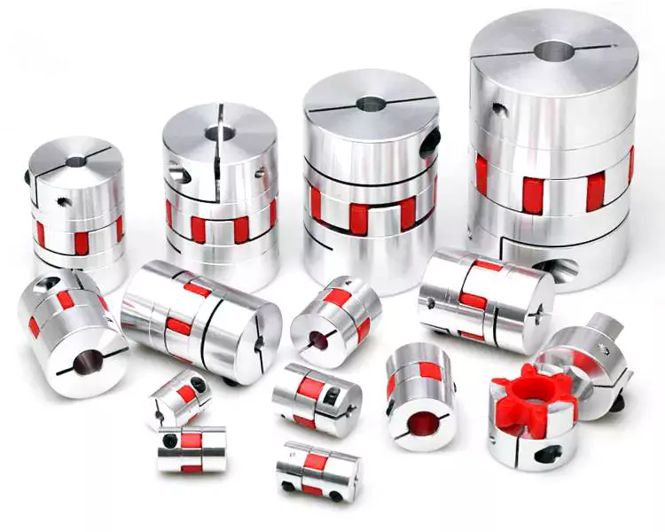
A coupling is a mechanical device that connects two shafts and transmits power. Its main purpose is to join two rotating pieces of equipment together, and it can also be used to allow some end movement or misalignment. There are many different types of couplings, each serving a specific purpose.
Functions
Functions of coupling are useful tools to study the dynamical interaction of systems. These functions have a wide range of applications, ranging from electrochemical processes to climate processes. The research being conducted on these functions is highly interdisciplinary, and experts from different fields are contributing to this issue. As such, this issue will be of interest to scientists and engineers in many fields, including electrical engineering, physics, and mathematics.
To ensure the proper coupling of data, coupling software must perform many essential functions. These include time interpolation and timing, and data exchange between the appropriate nodes. It should also guarantee that the time step of each model is divisible by the data exchange interval. This will ensure that the data exchange occurs at the proper times.
In addition to transferring power, couplings are also used in machinery. In general, couplings are used to join two rotating pieces. However, they can also have other functions, including compensating for misalignment, dampening axial motion, and absorbing shock. These functions determine the coupling type required.
The coupling strength can also be varied. For example, the strength of the coupling can change from negative to positive. This can affect the mode splitting width. Additionally, coupling strength is affected by fabrication imperfections. The strength of coupling can be controlled with laser non-thermal oxidation and water micro-infiltration, but these methods have limitations and are not reversible. Thus, the precise control of coupling strength remains a major challenge.
Applications
Couplings transmit power from a driver to the driven piece of equipment. The driver can be an electric motor, steam turbine, gearbox, fan, or pump. A coupling is often the weak link in a pump assembly, but replacing it is less expensive than replacing a sheared shaft.
Coupling functions have wide applications, including biomedical and electrical engineering. In this book, we review some of the most important developments and applications of coupling functions in these fields. We also discuss the future of the field and the implications of these discoveries. This is a comprehensive review of recent advances in coupling functions, and will help guide future research.
Adaptable couplings are another type of coupling. They are made up of a male and female spline in a polymeric material. They can be mounted using traditional keys, keyways, or taper bushings. For applications that require reversal, however, keyless couplings are preferable. Consider your process speed, maximum load capacity, and torque when choosing an adaptable coupling.
Coupling reactions are also used to make pharmaceutical products. These chemical reactions usually involve the joining of two chemical species. In most cases, a metal catalyst is used. The Ullmann reaction, for instance, is an important example of a hetero-coupling reaction. This reaction involves an organic halide with an organometallic compound. The result is a compound with the general formula R-M-R. Another important coupling reaction involves the Suzuki coupling, which unites two chemical species.
In engineering, couplings are mechanical devices that connect two shafts. Couplings are important because they enable the power to be transmitted from one end to the other without allowing a shaft to separate during operation. They also reduce maintenance time. Proper selection, installation, and maintenance, will reduce the amount of time needed to repair a coupling.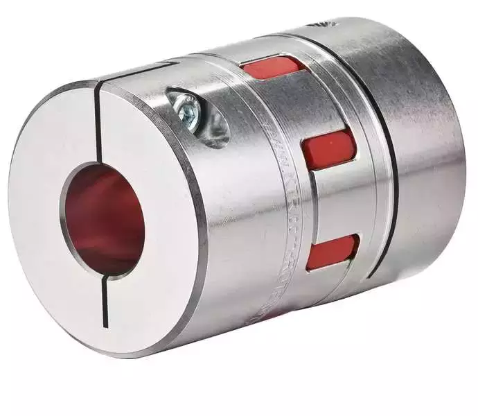
Maintenance
Maintenance of couplings is an important part of the lifecycle of your equipment. It’s important to ensure proper alignment and lubrication to keep them running smoothly. Inspecting your equipment for signs of wear can help you identify problems before they cause downtime. For instance, improper alignment can lead to uneven wear of the coupling’s hubs and grids. It can also cause the coupling to bind when you rotate the shaft manually. Proper maintenance will extend the life of your coupling.
Couplings should be inspected frequently and thoroughly. Inspections should go beyond alignment checks to identify problems and recommend appropriate repairs or replacements. Proper lubrication is important to protect the coupling from damage and can be easily identified using thermography or vibration analysis. In addition to lubrication, a coupling that lacks lubrication may require gaskets or sealing rings.
Proper maintenance of couplings will extend the life of the coupling by minimizing the likelihood of breakdowns. Proper maintenance will help you save money and time on repairs. A well-maintained coupling can be a valuable asset for your equipment and can increase productivity. By following the recommendations provided by your manufacturer, you can make sure your equipment is operating at peak performance.
Proper alignment and maintenance are critical for flexible couplings. Proper coupling alignment will maximize the life of your equipment. If you have a poorly aligned coupling, it may cause other components to fail. In some cases, this could result in costly downtime and increased costs for the company.
Proper maintenance of couplings should be done regularly to minimize costs and prevent downtime. Performing periodic inspections and lubrication will help you keep your equipment in top working order. In addition to the alignment and lubrication, you should also inspect the inside components for wear and alignment issues. If your coupling’s lubrication is not sufficient, it may lead to hardening and cracking. In addition, it’s possible to develop leaks that could cause damage.
Modifications
The aim of this paper is to investigate the effects of coupling modifications. It shows that such modifications can adversely affect the performance of the coupling mechanism. Moreover, the modifications can be predicted using chemical physics methods. The results presented here are not exhaustive and further research is needed to understand the effects of such coupling modifications.
The modifications to coupling involve nonlinear structural modifications. Four examples of such modifications are presented. Each is illustrated with example applications. Then, the results are verified through experimental and simulated case studies. The proposed methods are applicable to large and complex structures. They are applicable to a variety of engineering systems, including nonlinear systems.

editor by CX 2023-07-31
China High Rigid Stainless Steel Flexible Connector for Shaft and Motor Bellow Type Coupling bibliographic coupling
Solution Description
| Product No. | φD | L | L1 | L2 | M | Tighten the toughness(N.m) |
| SG7-6-40- | 40 | fifty five | 19 | 24 | M3 | 3 |
| SG7-6-55- | fifty five | sixty five | 22 | 31 | M4 | six |
| SG7-6-sixty five- | sixty five | seventy six | 27 | 37 | M5 | eight |
| SG7-6-eighty two- | 82 | 88 | 32 | forty one | M6 | ten |
| SG7-6-90- | 90 | 88 | 32 | forty one | M6 | twelve |
11111111111111111111111111111111111111111111111111111111111111111111111111111111111111111111111111111111111111111111111111111111111111111111111111111111111111111111111111111111111111111111111111111111111111111111111111111
1111111111111111111111111111111111111111111111111111111111111111111111111111111111111111111111111111111111111111111111111111111111111111111111111111111111111111111111111111111111111111111111111111111111111111111112111111111111111111111111111111111111111111111111111111111
| Merchandise No. | Rated torque | Optimum Torque | Max Pace | Inertia Minute | N.m rad | RRO | Tilting Tolerance | Conclude-enjoy | Weight:(g) |
| SG7-6-forty- | 13N.m | 26N.m | 8000prm | 9×10⁻⁵kg.m² | 15×103N.m/rad | .15mm | 2c | 1mm | 231 |
| SG7-6-fifty five- | 28N.m | 56N.m | 6000prm | two.9×10-4kg.m² | 28×103N.m/rad | .2mm | 2c | 1.5mm | 485 |
| SG7-6-65- | 60N.m | 120N.m | 5000prm | four.6×10-4kg.m² | 55×103N.m/rad | .25mm | 2c | 1.5mm | 787 |
| SG7-6-82- | 150N.m | 300N.m | 4500prm | one.1×10-3kg.m² | 110×103N.m/rad | .28mm | 2c | 1.5mm | 1512 |
| SG7-6-ninety- | 200N.m | 400N.m | 4000prm | 2×10⁻³kg.m² | 140×103N.m/rad | .3mm | 2c | one.5mm | 1800 |
|
US $30-52 / Piece | |
5 Pieces (Min. Order) |
###
| Standard Or Nonstandard: | Nonstandard |
|---|---|
| Shaft Hole: | Customized |
| Torque: | 13-200n.M |
| Bore Diameter: | Customized |
| Speed: | 8000-4000rpm |
| Structure: | Flexible |
###
| Item No. | φD | L | L1 | L2 | M | Tighten the strength(N.m) |
| SG7-6-40- | 40 | 55 | 19 | 24 | M3 | 3 |
| SG7-6-55- | 55 | 65 | 22 | 31 | M4 | 6 |
| SG7-6-65- | 65 | 76 | 27 | 37 | M5 | 8 |
| SG7-6-82- | 82 | 88 | 32 | 41 | M6 | 10 |
| SG7-6-90- | 90 | 88 | 32 | 41 | M6 | 12 |
###
| Item No. | Rated torque | Maximum Torque | Max Speed | Inertia Moment | N.m rad | RRO | Tilting Tolerance | End-play | Weight:(g) |
| SG7-6-40- | 13N.m | 26N.m | 8000prm | 9×10⁻⁵kg.m² | 15×103N.m/rad | 0.15mm | 2c | 1mm | 231 |
| SG7-6-55- | 28N.m | 56N.m | 6000prm | 2.9×10⁻⁴kg.m² | 28×103N.m/rad | 0.2mm | 2c | 1.5mm | 485 |
| SG7-6-65- | 60N.m | 120N.m | 5000prm | 4.6×10⁻⁴kg.m² | 55×103N.m/rad | 0.25mm | 2c | 1.5mm | 787 |
| SG7-6-82- | 150N.m | 300N.m | 4500prm | 1.1×10⁻³kg.m² | 110×103N.m/rad | 0.28mm | 2c | 1.5mm | 1512 |
| SG7-6-90- | 200N.m | 400N.m | 4000prm | 2×10⁻³kg.m² | 140×103N.m/rad | 0.3mm | 2c | 1.5mm | 1800 |
Types of Couplings
A coupling is a device used to join two shafts together and transmit power. Its purpose is to join rotating equipment while permitting a degree of end movement and misalignment. There are many types of couplings, and it is important to choose the right one for your application. Here are a few examples of couplings.
Mechanical
The mechanical coupling is an important component in power transmission systems. These couplings come in various forms and can be used in different types of applications. They can be flexible or rigid and operate in compression or shear. In some cases, they are permanently attached to the shaft, while in other cases, they are removable for service.
The simplest type of mechanical coupling is the sleeve coupling. It consists of a cylindrical sleeve with an internal diameter equal to the diameter of the shafts. The sleeve is connected to the shafts by a key that restricts their relative motion and prevents slippage. A few sleeve couplings also have threaded holes to prevent axial movement. This type of coupling is typically used for medium to light-duty torque.
Another type of mechanical coupling is a jaw coupling. It is used in motion control and general low-power transmission applications. This type of coupling does not require lubrication and is capable of accommodating angular misalignment. Unlike other types of couplings, the jaw coupling uses two hubs with intermeshing jaws. The jaw coupling’s spider is typically made of copper alloys. In addition, it is suitable for shock and vibration loads.
Mechanical couplings can be made from a variety of materials. One popular choice is rubber. The material can be natural or chloroprene. These materials are flexible and can tolerate slight misalignment.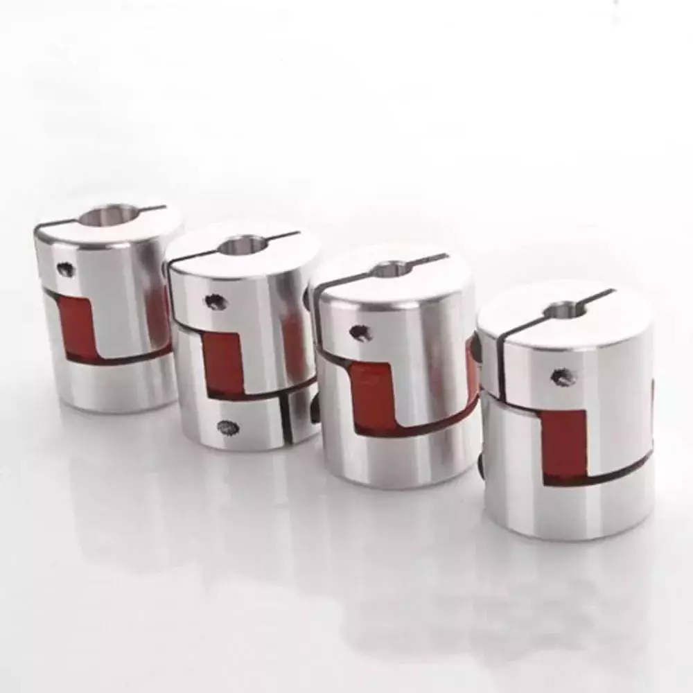
Electrical
Electrical coupling is the process in which a single electrical signal is transferred from a nerve cell to another. It occurs when electrical signals from two nerve cells interact with each other in a way similar to haptic transmission. This type of coupling can occur on its own or in combination with electrotonic coupling in gap junctions.
Electrical coupling is often associated with oscillatory behavior of neurons. The mechanism of electrical coupling is complex and is studied mathematically to understand its effect on oscillatory neuron networks. For example, electrical coupling can increase or decrease the frequency of an oscillator, depending on the state of the neuron coupled to it.
The site of coupling is usually the junction of opposing cell membranes. The cellular resistance and the coupling resistance are measured in voltage-clamp experiments. This type of coupling has a specific resistance of 100 O-cm. As a result, the coupling resistance varies with the frequency.
The authors of this study noted that electrotonic coupling depends on the ratio between the resistance of the nonjunctional membranes and the junctional membranes. The voltage attenuation technique helps reveal the differences in resistance and shunting through the intercellular medium. However, it is unclear whether electrotonic coupling is electrostatically mediated.
Electrical coupling has also been suggested to play a role in the intercellular transfer of information. There are many examples that support this theory. A message can be a distinct qualitative or quantitative signal, which results in a gradient in the cells. Although gap junctions are absent at many embryonic interaction sites, increasing evidence suggests a role in information transfer.
Flexible
When it comes to choosing the right Flexible Coupling, there are several factors that you should take into account. Among these factors is the backlash that can be caused by the movement of the coupling. The reason for this problem is the fact that couplings that do not have anti-fungal properties can be easily infected by mold. The best way to avoid this is to pay attention to the moisture content of the area where you are installing the coupling. By following these guidelines, you can ensure the best possible installation.
To ensure that you are getting the most out of your flexible couplings, you must consider their characteristics and how easy they are to install, assemble, and maintain. You should also look for elements that are field-replaceable. Another important factor is the coupling’s torsional rigidity. It should also be able to handle reactionary loads caused by misalignment.
Flexible couplings come in many different types. There are diaphragm and spiral couplings. These couplings allow for axial motion, angular misalignment, and parallel offset. They have one-piece construction and are made from stainless steel or aluminum. These couplings also offer high torsional stiffness, which is beneficial for applications requiring high torques.
Flexible couplings have several advantages over their rigid counterparts. They are designed to handle misalignments of up to seven degrees and 0.025 inches. These characteristics are important in motion control applications. Flexible couplings are also inexpensive, and they do not require maintenance.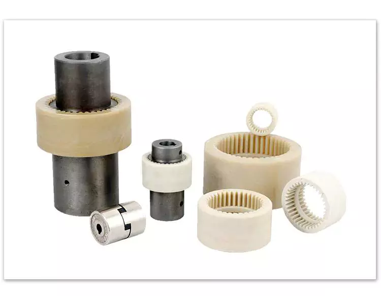
Beam
A beam coupling is a type of mechanical coupling, usually one solid piece, that connects two mechanical parts. Its performance is largely determined by the material used. Typical materials include stainless steel, aluminum, Delrin, and titanium. The beam coupling is rated for different speeds and torques. The coupling should be selected according to the application. In addition to the material, the application should also consider the speed and torque of the system.
There are two main types of beam couplings. The first is the helical beam coupling, which has a continuous multi spiral cut. This type of coupling offers a high degree of flexibility and compensates for a high degree of misalignment. The second type of beam coupling is the helical shaft coupling, which has a low torsional stiffness, which makes it ideal for small torque applications.
Another type of beam coupling is the multiple beam design, which combines two beams. It allows for more tolerance in manufacturing and installation and protects expensive components from excessive bearing loads. It also helps keep beams shorter than a single beam coupling. This type of coupling also enables a higher torque capacity and torsional stiffness.
Beam couplings can be manufactured with different materials, including stainless steel and aluminum. The “A” series is available in aluminum and stainless steel and is ideal for general-purpose and light-duty applications. It is also economical and durable. This type of coupling can also be used with low torque pumps or encoder/resolver systems.
Pin & bush
The Pin & bush coupling is a versatile, general-purpose coupling with high tensile bolts and rubber bushes. It can tolerate a wide range of operating temperatures and is suitable for use in oil and water-resistance applications. Its unique design enables it to be used in either direction. In addition, it requires no lubrication.
The pin bush coupling is a fail-safe coupling with a long service life and is used for high-torque applications. It provides torsional flexibility and dampens shocks, making it a flexible coupling that protects equipment and reduces maintenance costs. Its hubs are forged from graded cast iron for strength and durability. Besides, the coupling’s elastomer elements reduce vibration and impact loads. It also accommodates a misalignment of up to 0.5 degrees.
Pin & bush couplings are a popular choice for a variety of different applications. This coupling features a protective flange design that protects the coupling flange from wear and tear. The coupling nut is secured to one flange, while a rubber or leather bush sits between the other flange. Its unique design makes it ideal for use in applications where misalignment is a small factor. The rubber bushing also helps absorb vibration and shock.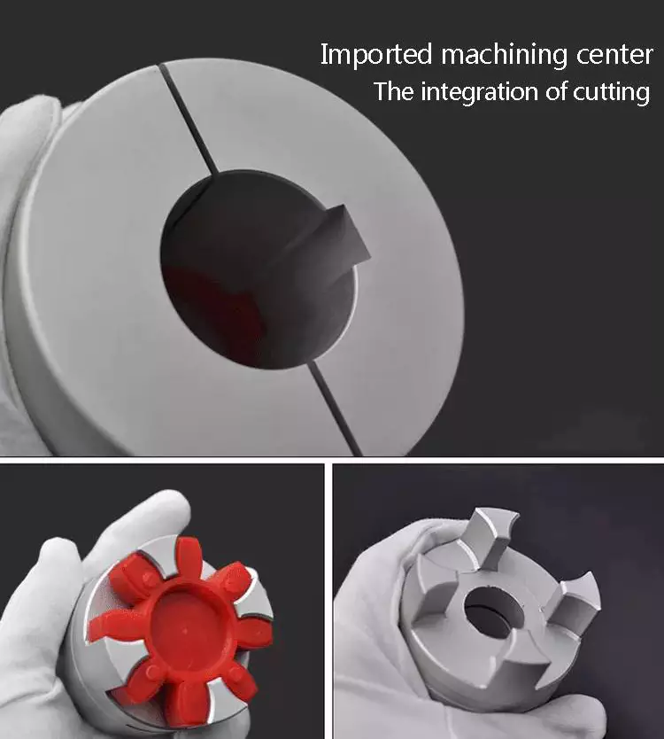
Mesh tooth
Mesh tooth couplings are used to transfer torque between two shafts and reduce backlash. However, mesh tooth couplings have some limitations. One disadvantage is the break-away friction factor in the axial direction. This problem is caused by the high contact force between the tooth and gear mesh. This can cause unpredictable forces on the shafts.
In this paper, we present a FEM model for mesh tooth coupling. We first validate the mesh density. To do so, we compute the bolt stress as a uniaxial tensile during the tightening process. We used different mesh sizes and mesh density to validate our results.
The mesh stiffness of gear pairs is influenced by lead crown relief and misalignment. For example, if one tooth is positioned too far in the axis, the mesh stiffness will be decreased. A misaligned gear pair will lose torque capacity. A mesh tooth coupling can be lubricated with oil.
An ideal mesh tooth coupling has no gaps between the teeth, which reduces the risk of uneven wear. The coupling’s quality exposed fasteners include SAE Grade 5 bolts. It also offers corrosion resistance. The couplings are compatible with industrial environments. They also eliminate the need for selective assembly in sleeve couplings.

editor by czh 2022-12-20
China Professional Supplier of Flexible Coupling, Jaw Coupling, Motor Coupling coupling brass
Item Description
Expert supplier of Versatile coupling,Jaw coupling,Motor coupling
Quick Details
Structure: Jaw / Spider
Adaptable or Rigid: Versatile
Common or Nonstandard: Standard
Content: Aluminium
Model Variety: JM-C
Spider colour: Crimson (Environmentally friendly and Yellow chosen)
Specs
1.The resources of Spider:German Bayer.
2.Hard Aluminum alloy
Your kind reaction of below concerns will aid us to recomemnd the most appropriate model to you asap.
1.Areyou hunting for Setscrew variety or Clamp type?
two.what is coupling outer dimeter measurement?
3.what is coupling inner bore measurement and size?
4.what is coupling materials(aluminium or Stainless steel )?
Dimensions:
| Design | Inner bore | D (mm) |
L (mm) |
Nominal Torque (N.m) |
The Max of Torque (N.m) |
|
| dmin | dmax | |||||
| JM2-twenty five | four | 12 | twenty five | 34 | 5. | ten. |
| JM2-thirty | 6 | 16 | thirty | 35 | 7.four | fourteen.eight |
| JM2-40 | ten | 24 | 40 | 66 | 9.five | 19. |
| JM2-fifty five | 12 | 28 | fifty five | 78 | 34 | 68 |
| JM2-sixty five | fourteen | 38 | 65 | 90 | 95 | one hundred ninety |
| JM2-eighty | 24 | forty five | 80 | 114 | a hundred thirty five | 270 |
| JM2-95 | thirty | 55 | ninety five | 126 | 230 | 460 |
| JM2-one hundred and five | 35 | sixty | one zero five | one hundred forty | 380 | 760 |
| Product | Allowable speed (rpm) |
Radial Misalignment(m.m) | Angular Misalignment(°) |
Axle Misalignment(mm) |
||
| JM2-twenty five | 17000 | .02 | 1. | +.sixty | ||
| JM2-30 | 12000 | .02 | 1. | +.sixty | ||
| JM2-40 | ten thousand | .02 | one. | +.eighty | ||
| JM2-fifty five | 8000 | .02 | one. | +.80 | ||
| JM2-sixty five | 6000 | .02 | 1. | +.eighty | ||
| JM2-eighty | 4600 | .02 | one. | +1.00 | ||
| JM2-95 | 3800 | .02 | 1. | +1.00 | ||
| JM2-105 | 3400 | .02 | 1. | |||
Packaging Specifics:
Wood or ply situations for export standard or according to the buyers
Shipping and delivery Element:3-5 times soon after acquiring the thirty% deposit
| Type: | Wooden Mold Router |
|---|---|
| Feed Mode: | Mechanical |
| Controlling Mode: | CNC |
| Customized: | Customized |
| Cetrification: | ISO 9001:2008 |
| Place of Origin: | Shandong China |
###
| Customization: |
Available
|
|---|
###
| Model | Inner bore | D (mm) |
L (mm) |
Nominal Torque (N.m) |
The Max of Torque (N.m) |
|
| dmin | dmax | |||||
| JM2-25 | 4 | 12 | 25 | 34 | 5.0 | 10.0 |
| JM2-30 | 6 | 16 | 30 | 35 | 7.4 | 14.8 |
| JM2-40 | 10 | 24 | 40 | 66 | 9.5 | 19.0 |
| JM2-55 | 12 | 28 | 55 | 78 | 34 | 68 |
| JM2-65 | 14 | 38 | 65 | 90 | 95 | 190 |
| JM2-80 | 24 | 45 | 80 | 114 | 135 | 270 |
| JM2-95 | 30 | 55 | 95 | 126 | 230 | 460 |
| JM2-105 | 35 | 60 | 105 | 140 | 380 | 760 |
| Model | Allowable speed (rpm) |
Radial Misalignment(m.m) | Angular Misalignment(°) |
Axle Misalignment(mm) |
||
| JM2-25 | 17000 | 0.02 | 1.0 | +0.60 | ||
| JM2-30 | 12000 | 0.02 | 1.0 | +0.60 | ||
| JM2-40 | 10000 | 0.02 | 1.0 | +0.80 | ||
| JM2-55 | 8000 | 0.02 | 1.0 | +0.80 | ||
| JM2-65 | 6000 | 0.02 | 1.0 | +0.80 | ||
| JM2-80 | 4600 | 0.02 | 1.0 | +1.00 | ||
| JM2-95 | 3800 | 0.02 | 1.0 | +1.00 | ||
| JM2-105 | 3400 | 0.02 | 1.0 | |||
Types of Couplings
A coupling is a device that connects two shafts and transmits power from one to the other. Its main purpose is to join two pieces of rotating equipment. It also allows for some degree of misalignment or end movement. Here are a few examples of coupling types: Beam coupling, Flexible coupling, Magnetic coupling, and Shaft coupling.
Beam coupling
Beam couplings are used to couple motors and other devices. They are available in several types, including flexible, slit, and rigid beam couplings. Each has unique properties and characteristics. These couplings are best for applications requiring a high level of precision and long life. They are also a practical solution for the connection of stepping and servo motors with screw rods.
Beam couplings are usually made of stainless steel or aluminum alloy, and feature spiral and parallel cut designs. Multiple cuts allow the coupling to accommodate multiple beams and improve angular and parallel misalignment tolerances. Additionally, beam couplings are comparatively cheaper than other types of rotary joints, and they require minimal maintenance.
The materials of a beam coupling should be considered early in the specification process. They are typically made of aluminum or stainless steel, but they can also be manufactured from Delrin, titanium, and other engineering grade materials. Beam couplings are often available in multiple sizes to fit specific shaft diameters.
Beam couplings are a key component of motion control systems. They provide excellent characteristics when used properly, and they are a popular choice for many applications. A thorough understanding of each type of coupling will help to prevent coupling failure and enhance system performance. Therefore, it is important to choose the right coupling for your application.
Various types of beam couplings have unique advantages and disadvantages. The FCR/FSR design has two sets of three beams. It is available in both metric and inch shaft sizes. The FCR/FSR couplings are ideal for light-duty power transmission applications. A metric shaft is more suitable for these applications, while an inch shaft is preferred for heavier duty applications.
Two types of beam couplings are available from Ruland. The Ruland Flexible beam coupling has a multi-helical cut design that offers a greater flexibility than commodity beam couplings. This design allows for higher torque capabilities while minimizing wind-up. In addition, it is also more durable than its commodity counterparts.
Flexible coupling
A flexible coupling is a versatile mechanical connection that allows for the easy coupling of two moving parts. The design of these couplings allows for a variety of stiffness levels and can address a variety of problems, such as torsional vibrations or critical speed. However, there are a number of tradeoffs associated with flexible couplings.
One of the biggest issues is the installation of the coupling, which requires stretching. This problem can be exacerbated by cold temperatures. In such a case, it is vital to install the coupling properly. Using a gear clamp is one of the most important steps in a successful installation. A gear clamp will keep the coupling in place and prevent it from leaking.
Another common type of flexible coupling is the gear coupling. These couplings are composed of two hubs with crowned external gear teeth that mesh with two internally splined flanged sleeves. The massive size of the teeth makes them resemble gears. Gear couplings offer good torque characteristics but require periodic lubrication. These couplings can also be expensive and have a limited number of applications.
Another type of flexible coupling is the SDP/SI helical coupling. These couplings can accommodate axial motion, angular misalignment, and parallel offset. This design incorporates a spiral pattern that makes them flexible. These couplings are available in stainless steel and aluminum.
A flexible coupling has a wide range of applications. Generally, it is used to connect two rotating pieces of equipment. Depending on its design, it can be used to join two pieces of machinery that move in different directions. This type of coupling is a type of elastomeric coupling, which has elastic properties.
There are many types of flexible couplings available for different types of applications. The purpose of a flexible coupling is to transmit rotational power from one shaft to another. It is also useful for transmitting torque. However, it is important to note that not all flexible couplings are created equally. Make sure to use a reputable brand for your coupling needs. It will ensure a reliable connection.
The simplest and most commonly used type of flexible coupling is the grid coupling. This type of coupling uses two hubs with slotted surfaces. The steel grid is allowed to slide along these slots, which gives it the ability to flex. The only limitation of this type of coupling is that it can only tolerate a 1/3 degree misalignment. It can transmit torques up to 3,656 Nm.
Magnetic coupling
Magnetic coupling is a technique used to transfer torque from one shaft to another using a magnetic field. It is the most common type of coupling used in machinery. It is highly effective when transferring torque from a rotating motor to a rotating shaft. Magnetic couplings can handle high torques and high speeds.
Magnetic coupling is described by the energy difference between a high-spin state and a broken symmetry state, with the former being the energy of a true singlet state. In single-determinant theories, this energy difference is called the Kij. Usually, the broken-symmetry state is a state with two interacting local high-spin centers.
The magnetic coupling device is regarded as a qualitative leap in the reaction still industry. It has solved a number of problems that had plagued the industry, including flammability, explosiveness, and leakage. Magnetic couplings are a great solution for many applications. The chemical and pharmaceutical industries use them for various processes, including reaction stills.
Magnetic couplings are a good choice for harsh environments and for tight spaces. Their enclosed design keeps them fluid and dust-proof. They are also corrosion-resistant. In addition, magnetic couplings are more affordable than mechanical couplings, especially in areas where access is restricted. They are also popular for testing and temporary installations.
Another use for magnetic coupling is in touch screens. While touch screens use capacitive and resistive elements, magnetic coupling has found a cool new application in wireless charging. While the finger tracking on touch screens may seem like a boley job, the process is very sensitive. The devices that use wireless charging need to have very large coils that are locked into resonant magnetic coupling.
Magnetic couplings also help reduce hydraulic horsepower. They cushion starts and reduce alignment problems. They can also improve flow in oversized pumps. A magnetic coupling with an 8 percent air gap can reduce hydraulic HP by approximately 27 percent. In addition, they can be used in aggressive environments. They also help reduce repair costs.
Magnetic couplings are a great choice for pumps and propeller systems because they have the added advantage of being watertight and preventing shaft failure. These systems also have the benefit of not requiring rotating seals.
Shaft coupling
A shaft coupling joins two shafts and transmits rotational motion. Generally, shaft couplings allow for some degree of misalignment, but there are also torque limiters. Selecting the right coupling can save you time and money and prevent equipment downtime. Here are the main features to consider when purchasing a coupling for your application.
Shaft couplings should be easy to install and disassemble, transmit full power to the mated shaft, and reduce shock loads. A shaft coupling that does not have projecting parts should be used for machines that move or rotate at high speeds. Some types of shaft couplings are flexible while others are rigid.
Shaft couplings can be used in a variety of applications, including piping systems. They can be used to connect shafts that are misaligned and help maintain alignment. They can also be used for vibration dampening. Shaft couplings also allow shafts to be disconnected when necessary.
Shaft couplings can accommodate a certain amount of backlash, but this backlash must be well within the tolerance set by the system. Extremely high backlash can break the coupling and cause excessive wear and stress. In addition, excessive backlash can lead to erratic alignment readings. To avoid these issues, operators must reduce backlash to less than 2deg.
Shaft couplings are often referred to by different names. Some are referred to as “sliced” couplings while others are known as “slit” couplings. Both types offer high torque and torsional stiffness. These couplings are typically made from metals with various alloys, such as acetal, stainless steel, or titanium.
CZPT Pulley produces shaft couplings for a variety of applications. These products are used in high-power transmission systems. They have several advantages over friction couplings. In addition to minimizing wear, they don’t require lubrication. They are also capable of transmitting high torque and high speeds.
Another type of shaft coupling is the universal coupling. It is used to transmit power to multiple machines with different spindles. Its keyed receiving side and flanges allow it to transmit power from one machine to another.

editor by czh 2022-11-27
China manufacturer & factory supplier for KM in Memphis United States Series 1:40 Ratio 90 Degree Hypoid Gearbox with electric motor With high quality best price & service

WOur factory has acquired the certification of China’s Farm Machinery Merchandise Quality Authentication promulgated by the Farm Machinery Merchandise Top quality Authentication Centre of China. e’ve developed up our solution variety to react to the vastly different conditions located in diverse industrial environments close to the globe. From weighty industry to precision production, we function with conclude-customers in practically each sector and have professional options which are confirmed to offer a distinctive overall performance edge for your software.The group has taken component in the making and revising of ISO/TC100 worldwide chain normal many years in success and hosted the sixteenth ISO/TC100 International yearly meeting in 2004.
Overview
Quick Particulars
- Relevant Industries:
-
Building Materials Retailers, Production Plant, Equipment Restore Shops, Farms, Building works , Food & Beverage Stores
- Ratio:
-
up to thirty
- Mounting PositiA seal-journal floor that attributes an inverted shot-peened texture, with lifted (fairly than indented) spherical lobes and corresponding valleys in among, better supports hydrodynamic lubrication. EPT developed a process that compresses seal journals among burnishing dies that have been peened to generate random spherical depressions. This leaves an “orange peel” texture on the journal floor, typically with a twenty to forty-m in. floor roughness.on:
-
Foot Mounted,flange Mounted
- Gear material:
-
20CrMnTi Metal
- Housing Substance:
-
Aluminium &solid iron
- Warmth therapy:
-
Normalizing,carburizing,substantial-frequency heating,quenching
- Guarantee:
-
12 Months
- Bearing:
-
NSK,HRB,ZWZ,C&U,and many others
- Certification:
-
ISO9001:2015,ISO14001:2015
- Shade:
-
Blue,gray
Offer Capability
- Provide Capacity:
- one thousand Piece/Items per Month
Packaging & Shipping and delivery
- Packaging Particulars
- Plywood scenario
- Port
- Ningbo,Shanghai
-
Lead Time
: -
The lemon tube is appropriate for transmissible energy of sixteen-35HP, it is the chosen choice for substantial speeds and minimal torque transmission. The two-lobe lemon tube grants reduced vibrations up to 2600 rpm with lengths not exceeding 800mm. AC series with 6-lobe tubes (star) Quantity(Packing containers) one – ten >10 Est. Time(times) fifteen To be negotiated
On the internet Customization



 Q: Are you buying and selling business or manufacturer ?
A: We At any time-Power Team 1 of the greatest transmission suppliers in the entire world are factory.
Q: How extended is your shipping and delivery time?
A: Usually it is 5-10 times if the goods are in stock. or it is fifteen-twenty days if the merchandise are not in stock.
Q: Can we buy 1 pc of every single item for high quality tests?
A: Sure, we are happy to settle for trial get for high quality screening.
Q: What is your terms of payment ?
A: Payment=1000USD, 30% T/T in advance, harmony ahead of shippment.
If you have other issue, freely to speak to us,you should.


China manufacturer & factory supplier for NMRV030 in Leicester United Kingdom 60 Watt 24VDC Worm Gear Motor High Torque Gearbox Ratio 80 1 Speed Reducer With high quality best price & service
Competence for industriShear bolt torque limiter (SB) EPG Group delivers higher quality PTO shafts with tubes fastened by spring pin, cross joints with roller bearings with rollersal chains and sprockets It is our every day obstacle to source our buyers with the optimal solution – that means optimum for the required application and for the customers’ specific requirements. In some circumstances it indicates that we truly produce and manufacture very specific chain varieties for a single particular consumer. In order to be able to do so, three items are important:EPG is a skilled manufacturer and exporter that is anxious with the style, advancement and generation.
Overview
Rapid Information
- Applicable Industries:
-
Producing Plant
- Spot of Origin:Zhejiang, China
- Product NO:
-
SYF
- Colour:
-
Customer Ask for
- Ratio:
-
5-one hundred
- Material:
-
Aluminium Alloy
- Warranty:
-
one-2 Years
- Certificate:
-
ISO9001
- Bearing:
-
NSK Bearing
- Heat remedy:
-
fifty eight-sixty two HRC
- Output Type:
-
Hollow Sahft Output
- Equipment content:
-
forty five# Cast Metal
Packaging & Delivery
-
Guide Time
: -
Quantity(Baggage) 1 – 2 three – 10 >10 Est. Time(days) 3 8 To be negotiated
On the web Customization


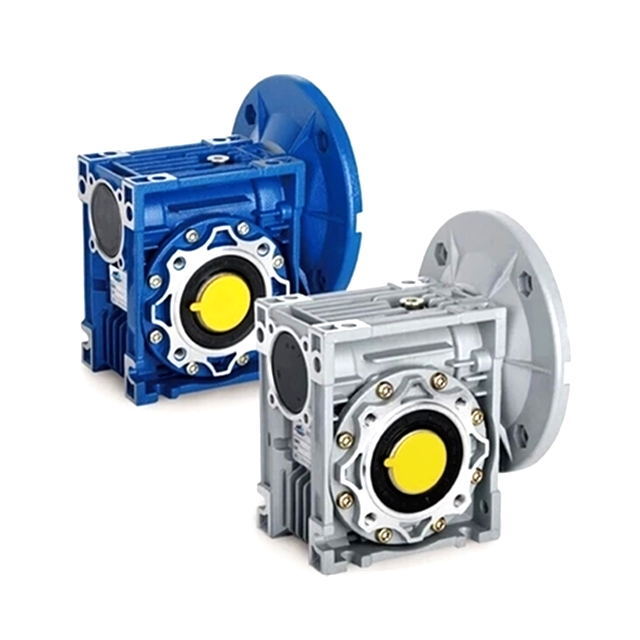
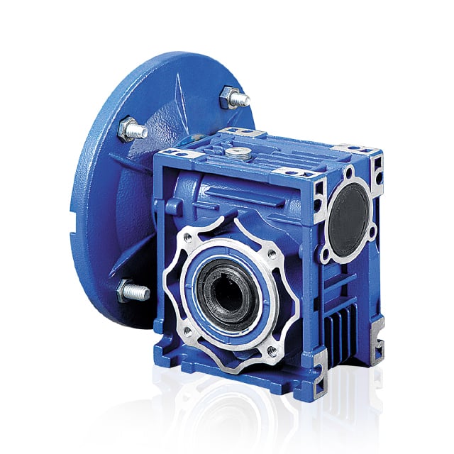
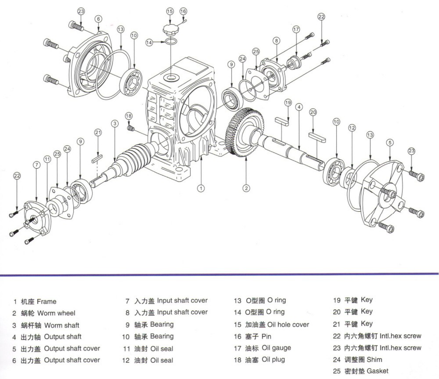
NMRV worm gearbox reducer is a commodity with refined layout and steady enhancements, its principal characteristics are manufactured of higher good quality aluminum alloy, light-weight excess weight and non-rusting, larget output toque, clean running and reduced noise, large radiating efficiency, great looking apprearance, derable support daily life, small volume and ideal for all mounting positions.

|
Output Torque |
one.8-1760Nm |
|
Software |
Equipment Sector |
|
Gear Material |
Zepgn12-2 (BS-1400 Grade-PB2) |
|
Input Pace |
900-2800RPM |
|
Output Pace |
10-250RPM |



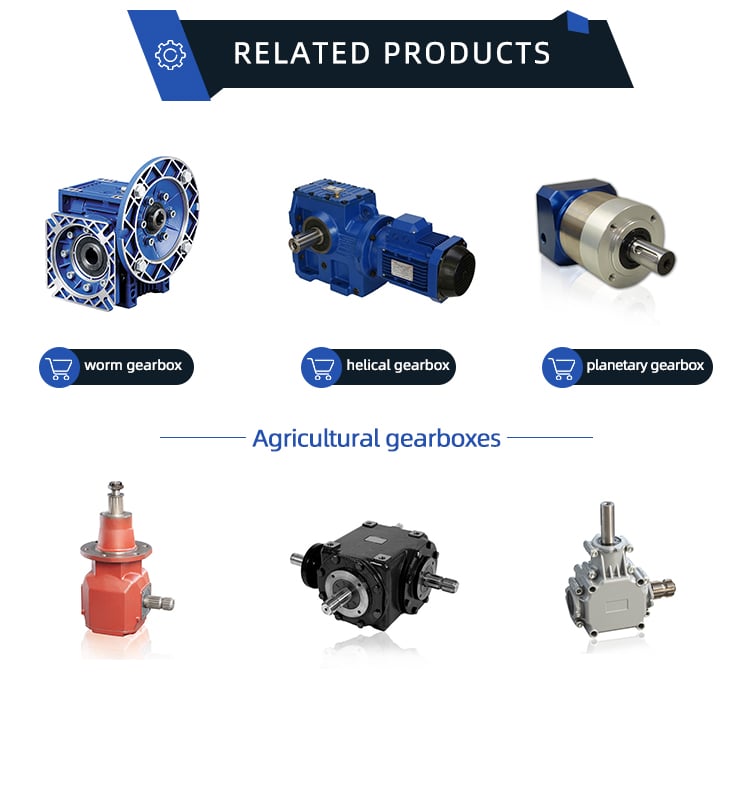
Principal products incorporate: manure spreading truck, potato planting/harvesting equipment, disc plough, disc harrow, grass Mower/slasher, corn and wheat thershers, seeder, mouldboard plow, deep subsoiler machines, rotary tiller, rear blade, fertilizer spreader, merge rice harvester, corn thresher, farm trailer, ridger, trencher, stubble cleaner, earth auger, cultivator and its accessories: Plow disc blades, harrowing film, plough tip and share, cultivator tine, casting parts and so on.
Relevant item


Company Profile


Packing & Shipping and delivery


